
Please see publication in Nature Scientific Reports (2015) (PDF download available there)
Modern cameras cannot see through fog, in the dark, or through walls, which make tasks such as driverless vehicles and search-and-rescue difficult. Where visible-light fails, radio-waves can easily penetrate these obstructions, however radar-imaging devices are complex, low-resolution, and unable to image certain geometries and angled surfaces. This paper takes a camera-like approach to microwave-imaging, resulting in a simpler camera architecture which can capture fuller 3D images through-walls.
Visible light has a wavelength between 390nm and 700nm, while our camera sees between 2.5cm and 4cm (much larger). While classical radar-imaging devices can perform these tasks, they do so with highly complex systems which are out of the reach of the consumer. We introduce a radar imaging architecture which makes imaging at these long wavelengths more accessible, while enabling all of the following:
- higher resolution imaging
- all of the electronics constrained to a small 10” x 10” space
- Fewer detectors necessary
- Better detection of specular (mirror-like) surfaces
- Multi-spectral imaging
- Time-resolved imaging (capturing Microwaves in flight)
The aim of our work is not just to detect objects, but also to form images in 3D. There are many advantages to being able to see how many limbs a person has and how tall they are; not just in what general area they are located. In order to image at such large wavelengths, sensors must cover a very large aperture at a high enough density to sufficiently sample the reflected waves (and prevent aliasing). Classical radar setups utilize hundreds of thousands of sensors to cover a large aperture at an appropriate density.
The future of commercial systems cannot rely on such large setups because they are difficult to produce and handle. Instead of spreading our electronics across the entire aperture, we focus all of our electronics to a 10” x 10” space, and use a large passive reflector to focus the reflected energy to this small area. Our setup enables higher resolution radar imaging by covering a large aperture with a passive-element, and constraining all of the electronics to a small focal plane. This architecture is useful for situations where many electronics are focused to a small area (such as a chip), since all that is necessary to increase the resolution of the device is to introduce a passive lens.
In addition to the resolution advantage of our architecture, our paper explores other challenges associated with microwave imaging. The wavelength of light we are imaging with is on the same order of size as the objects and features we are trying to image. At these large wavelengths, surfaces which normally appear diffuse appear mirror-like when viewed by microwaves. This causes normal objects to reflect light in ways that don’t return to the camera. In order to overcome this, our camera utilizes multiple flashes to capture surfaces which would normally appear stealth.
Our camera has a time resolution of 200ps (the time it takes microwaves to travel 6 cm). This enables the camera to capture the 3D location of objects, as well as to observe physical phenomena such as creeping waves, which can be used to determine if an object is made up of metal or not.
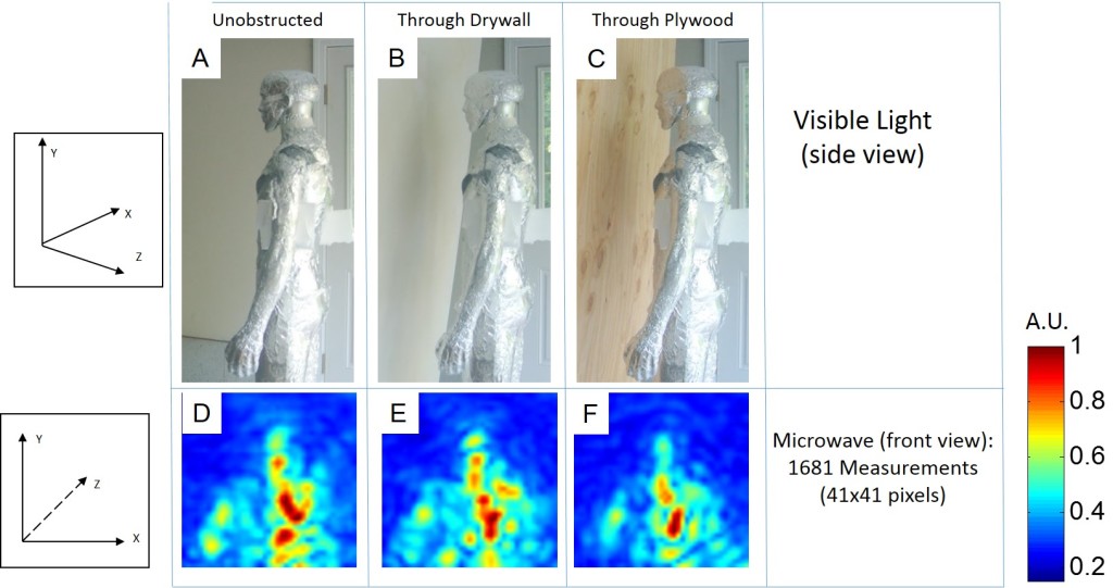
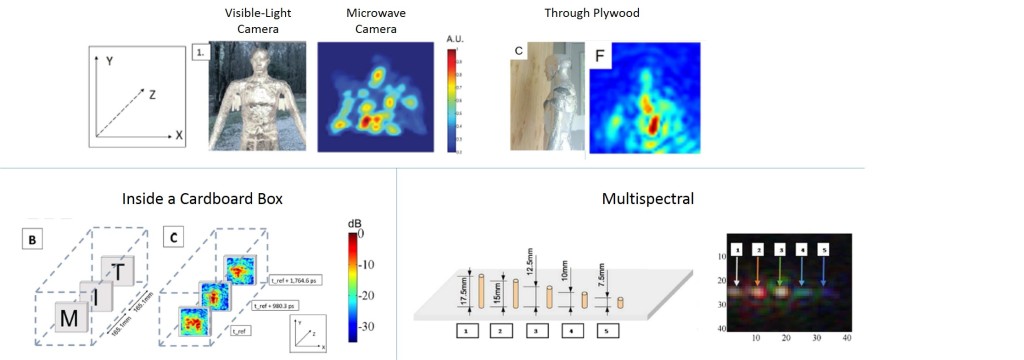
The microwave camera can image at wavelengths which easily penetrate drywall and plywood. In (A), (B), and (C) an image is taken of a mannequin wrapped in aluminum foil in free-space, placed behind 12.7 mm thick dry-wall, and behind 11.9 mm thick plywood. The mannequin is wrapped in foil in order to approximate the strong reflectivity of the human body23. The recovered 41 pixel by 41 pixel microwave-photographs are shown below each visible-light image (D—F).
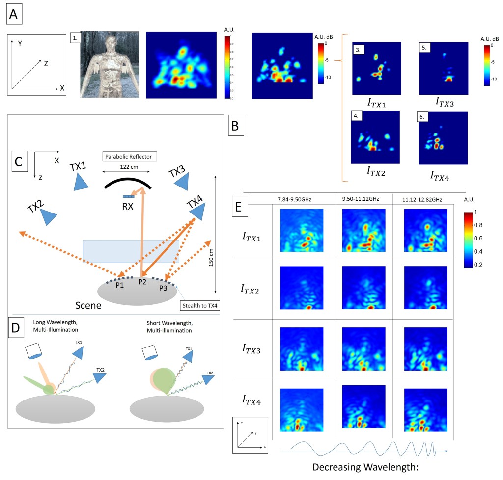
Can we recover diffuse-like images at microwave wavelengths? Combining images from multiple illumination sources creates microwave images with fewer stealth regions. In (A) we see a visible-light image (A1) and a microwave image of an unobscured mannequin (A2, A3) generated by projective recombination of illumination images (B1—4). In (C) the transmitters are on the left and right of the parabolic reflector. Incident rays from TX4 reflect off of P1 and P3, and never return to the camera; however, the reflection from P2 does return and is visible to the camera. Introducing other illumination points allows P1 and P3 to be visible to the camera. In (D) the reflectance lobes for short wavelengths are wider than the reflectance lobes at long wavelengths31, thus the multi-spectral images of the scene provide additional information depending on the size of features in the scene. In (E) each image is broken down into the energy received from three spectral bands, leading to diversity in reflectance properties.
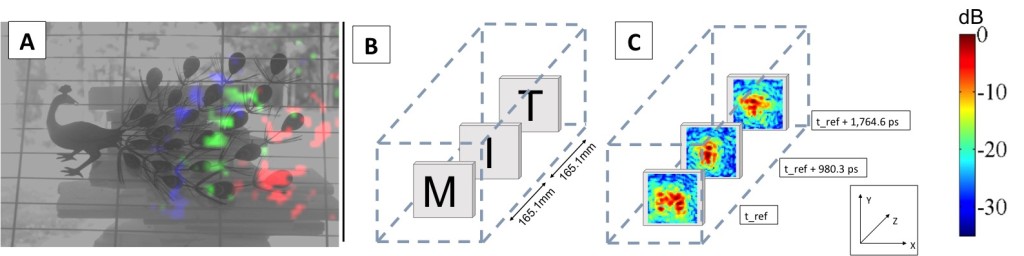
Two practical applications of a time-of-flight microwave camera are demonstrated. In (A) we visualize the propagation of microwaves across a metal peacock ornament as a color-coded time sequence, similar to a “light in flight” movie18,22. Here a grayscale, visible-light image is overlaid with color-coded data from the microwave camera. The red channel is the response at an early reference time, the green channel is the response at an additional 588.2 ps, and the blue channel is the response 1078.4 ps after the reference time. One can see the curve of the microwave as it crosses the scene and reflects off of features. In (B) the microwave camera is used to inspect the contents of a box to ensure proper packaging. A set of push pins are placed on three pieces of styrofoam inside of a shipping box in the shape of the letters “M”, “I”, and “T”. By separating the images in time, it is possible to see the three different layers. In (C) the average intensity at 700 ps around each center point is shown.
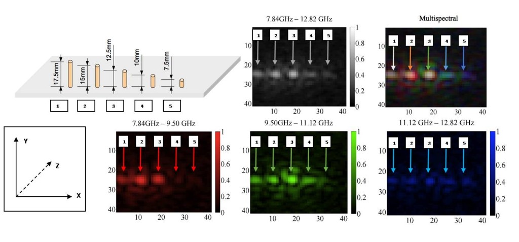
The illumination bandwidth can be exploited to generate multispectral microwave images. The reflectance properties of five sub-wavelength wire resonators of decreasing length are shown. In (A) there are five wires of decreasing length (L to R: 17.5 mm, 15 mm, 12.5 mm, 10 mm, and 7.5 mm) placed vertically in styrofoam (which is transparent in the X-band). In (B) a gray scale linear intensity image is shown (full 5 GHz bandwidth). In (C) a multi-spectral image is shown where the primary colors red, green, and blue represent the lower, middle, and upper frequency bands of illumination, respectively. The smaller wires are not as reflective of the longer wavelengths, causing them to appear bluer. The individual frequency band images are shown in (D—F).
Frequently Asked Questions:
Frequently Asked Questions:
How is this different from WiFi based tracking?
There is already a body of work on creating images in RF. While others track the position of a point, blob, or recognize course gestures, we create full 3D shapes.
Our work produces higher-resolution images than others have produced, from a system which does not surround the scene. In our images, one can see the head, torso, and arms of a mannequin. Furthermore, our systems use a greater bandwidth, thus enabling better time resolution (200 picoseconds).
How can you do that, and why haven’t others done that?
Our architecture takes a hybrid approach to microwaves and treats them like waves of light. Most other work places antennas in a 2D arrangement to directly sample the RF reflections that return. Due to system complexity constraints, it can be very costly to have a dense amount of antennas. Unfortunately, a dense number of antennas across a wide aperture is necessary to form high resolution images at long wavelengths (<24GHz RF signal).
Our work treats microwaves like light-waves. Instead of placing antennas in a 2D arrangment, we use a single, passive, parabolic reflector (dish) as a lens. You can think of every point on that dish as an antenna with a fixed phase-offset. This means that the lens acts as a fixed set of 2D antennas which are very dense and spaced across a large aperture. We then sample the focal-plane of that lens. This architecture makes it possible for us to capture higher resolution images at a lower cost.
So your camera is just a lens?
Short answer, no. While a lens enables you to take higher resolution RF pictures, we ran into many physical problems, which we were able to address using computational-imaging techniques. One issue we immediately saw when taking images was that in the RF world, most things are mirror-like, due to the long-wavelength of illumination. These mirror-like objects meant that if we used only 1 point of illumination, the image would be missing many surfaces. Inspired by photometric-stereo, we used multiple points of illumination to capture fuller images. This also resulted in information that enabled us to determine some of the orientation of the surfaces in the images we were capturing.
What else can the camera do?
- Since we are using active illumination with 200 picosecond time-resolution, we can capture images in 3D. That means we can time-gate responses which are too close, or too far from our area of interest.
- Our camera has a depth of field! That means that by changing the distance between the sensor and lens, we can control which distances are in-focus and out-of-focus.
- Our camera can see color in RF. The camera has a multispectral response, meaning we can see the differential response of materials at lower and higher frequencies. This can be used in material identification, just like color is used in a regular image.
- Our camera can see creeping-waves. This is a phenomenon caused by radio waves traveling around a surface and resonating. Since our camera has time-resolution, we can see these resonances in time. This can be used in the future to differentiate between metallic and non-metal objects
What’s up with the metal guy?
We ran all of our tests on objects and mannequins. Plastic mannequins are dielectrics and more-or-less transparent in RF. Human beings, however, are made of water and are very reflective to RF. We covered the mannequins in aluminum foil to better approximate the response of people.
Why is the setup so big?
The setup is large because our wavelength is long (~3cm). RF transceivers are now available which can transmit at 60 GHz (5mm wavelength) and are coming down in price. This would reduce the size of our camera to 10″ x 10″.
Where can this camera be used?
We envision the camera used for search and rescue, allowing for people to be seen through rubble and firefighters to detect if there are occupants in buildings. We also see the multi-flash aspect helping to improve navigation for driverless vehicles, which have trouble with fog. In addition, the work can be used for non-destructive evaluation and also user-interaction in an automated home.