In a conventional single-exposure photograph, moving objects or moving cameras cause motion blur. The exposure time defines a temporal box filter that smears the moving object across the image by convolution. This box filter destroys important high-frequency spatial details so that deblurring via deconvolution becomes an ill-posed problem.
Rather than leaving the shutter open for the entire exposure duration, we “flutter” the camera’s shutter open and closed during the chosen exposure time with a binary pseudo-random sequence. The flutter changes the box filter to a broad-band filter that preserves high-frequency spatial details in the blurred image and the corresponding deconvolution becomes a well-posed problem. We demonstrate that manually-specified point spread functions are sufficient for several challenging cases of motion-blur removal including extremely large motions, textured backgrounds and partial occluders.
Top left shows image of a fast moving taxi captured using our new camera. Bottom left shows the rectified image to make motion lines parallel to scan lines. An approximate cutout of the blurred object is shown in top right. The deblurred image obtained by solving a linear system is shown in bottom right. Note that all high frequencies are recovered and there are no deconvolution artifacts.
Key idea and differences with previous methods:
Motion deblurring is an ill-posed problem. The relative motion between camera and the scene results in a blurred image in which high frequencies are lost, due to which deblurring results in increased noise, ringing and other artifacts. Note that this is independent of the deblurring algorithm used. As soon as the image is captured, high frequencies are lost and the damage is done.
In this paper, we propose a novel coded exposure camera and show that by fluttering the shutter in a single exposure, one can retain high frequencies. The deblurring then become a well-posed problem. Our approach is thus fundamentally different from other deblurring algorithms. In fact, we use the simplest possible deconvolution approach: solving a linear system AX=B to recover the sharp image X from the blurred image B and show high quality results with large motion blurs (~300 pixels) with no ringing and deconvolution artifacts. The change in hardware amounts to putting an external ferro-electric shutter in front of the lens, synchronized with the start of the exposure time and can be done on any off the shelf digital camera.
Comparison of Short Exposure, Traditional Camera, and Coded Exposure Camera
Our portable prototype camera
Picture taken with a traditional camera
Picture taken with our camera
The above two images shows comparison of images taken with a traditional camera and coded exposure camera. A bright LED (light emitting diode) is moved rapidly in front of the camera by a person. For traditional camera, the image of LED is a continuous smear (on left). For coded exposure, due to fluttering of the shutter, the smear becomes discontinuous preserving high frequencies (on right).
A compact, fast CAT scan machine using no mechanical moving parts or synchronization.
We are creating a portable and high-speed tomography machine. We record all the data in a single snapshot without mechanical movement or time-division multiplexing of emitters.
Next Generation CAT-Scan Machines
General computed axial tomography(CAT or CAT-scan) acquires 3D views of a volume. The usage has been limited to specific professional applications in medical, industrial and security fields. There are two main reasons (i) X-ray sources are complex and hazardous and (ii) The machines require mechanical scanning. The fundamental concepts have remained the same for several decades and still involve highly complex machinery (See video).
We are using optical and mathematical insight to design a novel CAT-scan machine. Using spatial heterodyning principles, we exploit the sensor configuration and associated signal processing tools we have invented to recover a higher dimensional signal from lower dimensional sensor readings. In addition, we use a new generation of descattering methods from computational photography that can analyze and decompose direct component from global component. We have also built models to analyze light transport in scattering media.A sophisticated co-design of optical and digital processing will eliminate all moving parts and possibly allow us to use less harmful wavelengths. This will greatly simplify the design and allow us to build portable, always-on volumetric imaging devices. Beyond health screening and diagnostics, the ability to see inside our body will open up a range of applications in HCI, productivity and entertainment.
A novel super-resolution framework by exploring the properties of non-conventional pixel layouts and shapes.
We show that recording multiple images, transformed in the octic group, with a sensor of asymmetric sub-pixel layout increases the spatial sampling compared to a conventional sensor with a rectilinear grid of pixels and hence increases the image resolution. We further prove a theoretical bound for achieving well-posed super-resolution with a designated magnication factor w.r.t. the number and distribution of sub-pixels. We also propose strategies for selecting good sub-pixel layouts and effective super-resolution algorithms for our setup. The experimental results validate the proposed theory and solution, which have the potential to guide the future CCD layout design with super-resolution functionality.
Attenuation-corrected fluorescence spectra unmixing for spectroscopy and microscopy
Tensor factorization to decouple fluorescinig of multiple probes
In fluorescence measurements, light is often absorbed and scattered by a sample both for excitation and emission, resulting in the measured spectra to be distorted. Conventional linear unmixing methods computationally separate overlapping spectra but do not account for these effects. We propose a new algorithm for fluorescence unmixing that accounts for the attenuation-related distortion effect on fluorescence spectra. Using a matrix representation, we derive forward measurement formation and a corresponding inverse method; the unmixing algorithm is based on nonnegative matrix factorization. We also demonstrate how this method can be extended to a higher-dimensional tensor form, which is useful for unmixing overlapping spectra observed under the attenuation effect in spectral imaging microscopy. We evaluate the proposed methods in simulation and experiments and show that it outperforms a conventional, linear unmixing method when absorption and scattering contributes to the measured signals, as in deep tissue imaging.
By capturing and displaying a 4D light field, it can create arbitrary patterns directional illumination patterns and record their interaction with physical objects.
Compressive Analysis of Visual Signals
We analyze sampling strategies for reconstructing visual signals from a limited number of non-adaptive linear projections.
This could be a full decription about the project
Shield Fields
3D reconstruction of objects from a single shot photo using spacial heterodyning.
We describe a unified representation of occluders in light transport and photography using shield fields: the 4D attenuation function which acts on any light field incident on an occluder. Our key theoretical result is that shield fields can be used to decouple the effects of occluders from the incident illumination. We first describe the properties of shield fields in the frequency-domain and briefly analyze the “forward” problem of efficiently computing cast shadows. Afterwards, we apply the shield field signal-processing framework to make several new observations regarding the “inverse” problem of reconstructing 3D occluders from cast shadows – extending previous work on shape-from-silhouette and visual hull methods. From this analysis we develop the first single-camera, single-shot approach to capture visual hulls without requiring moving or programmable illumination. We analyze several competing camera designs – ultimately leading to the development of a new large-format, mask-based light field camera that exploits optimal tiled-broadband codes for light-efficient shield field capture. We conclude by presenting a detailed experimental analysis of shield field capture and 3D occluder reconstruction.
Tomographic techniques for image synthesis on displays composed of compact volumes of light-attenuating material. They can recreate 4D light field or high-contrast 2D image.
Efficient Rendering for Compressive Displays
Combining sampling, rendering, and display-specific optimization into a single framework, the algorithm facilitates light field synthesis with reduced computational resources.
Tailored Displays
A display that allows to free the viewer from needing wearable optical corrections when looking at it.
Take Your Glasses Off and See
Can we create a display that adapts itself to improve one’s eyesight? Top figure compares the view of a 2.5-diopter farsighted individual in regular and tailored displays. We use currently available inexpensive technologies to warp light fields to compensate for refractive errors and scattering sites in the eye.
Our new display uses measurements of refractive errors (see alsoNETRA) and cataract maps (see also CATRA) to free the viewer from needing wearable optical corrections when looking at displays. It supports nearsightedness, farsightedness, astigmatism, presbyopia(reading glasses), coma, keratoconus, other higher-order aberrationsand any type of cataracts. Knowledge of the eye conditions allows traditional displays go beyond an individual’s visual acuity, presenting images that are in focus even without wearing corrective eyeglasses. The hardware is the same of glasses-free 3D displays (dual stack of LCDs), but in higher resolution. We propose their use in daily tasks where using eyeglasses are unfeasible or inconvenient (e.g., on head-mounted displays, e-readers, as well as for games); when a multi-focus function is required but undoable (e.g., driving for farsighted individuals, checking a portable device while doing physical activities for presbyopic); or for correcting the visual distortions produced by high-order aberrations that eyeglasses are not able to.
Vitor F. Pamplona Interactive Measurements and Tailored Displays for Optical Aberrations of the Human Eye
PhD Thesis 2012. Draft Version.
Vitor F. Pamplona, Manuel M. Oliveira, Daniel G. Aliaga, Ramesh Raskar. Tailored Displays to Compensate for Visual Aberrations. ACM SIGGRAPH 2012. ACM Trans. on Graph. 31(4). Pages 87:1-12
Vitor F. Pamplona, Manuel M. Oliveira. Method and Aparatus for Displays that Compensate for Visual Aberrations.
BR / INPI.
SIGGRAPH Slide Set
Brief Technical Description
The letter G (a) on the retina of a 2D-coma, +5D-myopia (c), and cataract affected (d) subject. The holography G is virtualized at many depths (16cm < j < 25cm) from the eye. (b) shows how the image reaches the subject’s retina. (e) and (f) shows our computations for the light-field display. Giant ray circle reflects a 5mm-diameter pupil. Notice how the letter is deformed behind each section. Greenish circles in (e) and (f) highlight the cataract-avoiding feature of our algorithm.
We introduce tailored displays that enhance visual acuity by decomposing virtual objects and placing the resulting anisotropic pieces into the subject’s focal range. Our tailoring process uses aberration andscattering maps to account for refractive errors and cataracts. It splits an object’s light field into multiple instances that are each in-focus for a given eye subaperture. Their integration onto the retina leads to a quality improvement of perceived images when observing the display with naked eyes. The use of multiple depths to render each point of focus on the retina creates multi-focus, multi-depth displays. User evaluations and validation with modified camera optics are performed.
We call tailoring the process of adapting a light field to compensate for an individual’s inability to focus. We pre-warp the light field to counter act the distortion on the subject’s eyes. It is performed in two main steps: (i) pairing light-field rays and retinal positions (R) to associate a raw intensity to each ray; and (ii) normalizing retinal “pixels”. Given as input an expected image to be received by the retina and wavefront andcataract maps of the subject’s eye, the method produces a light field to be shown on a specified display. Our approach can be described as the projection of depth-dependent anisotropic patterns according to the spatially-distributed optical aberrations of the eye. The depth-dependent patterns are “anisotropic images” virtually placed at the right point in focus for a given optical power in a section for the cornea. Because these images are placed at multiple depths to create a single image in focus, we say our system has a multi-depth feature. Our method makes sure the depth-dependent patchs are seen only through eye sub-apertures with given refractive powers. Light paths that go through opacities or unpredictable scattering sites, such as cataracts, are avoided. The final result is a light field to be displayed at a given distance from the eye.
Acuity enhancement options range from simple eyeglasses to optical replacements and expensive relays for adaptive optics. They are grouped according to the correction bearer. Eyeglasses with simple, bifocal, and multi-focal lenses, contact lenses, LASIK and cataract surgeries can be used to enhance visual acuity. However, all of them require wearing prosthesis or making incisions in the eye. Multi-focus displays and holograms can enhance visual acuity by projecting images on the subject’s range of accommodation. These techniques, however, do not account for the subject’s individual variability. This paper proposes a new type of display that adjusts itself to compensate the subject’s eye refractive errors and avoids light scattering materials on the optical path, such as cataracts. The display is to some extent similar to a still-under-research adaptive-optics-based contact lenses, but applied to the device instead of the eye.
Potential Impact
Cataracts and refractive errors are the main causes of loss of visual acuity and leading causes of avoidable blindness worldwide. Approximately two billion people need eyeglasses (WHO – Vision 2020 Report) and the prevalence of both conditions are expected to grow with the increasing longevity and heavy near work, such as the use of electronic gadgets. For instance, in urban areas of east Asia, 80-90% of children completing high school are now myopic. People with absence of refractive errors and cataracts – i.e., normal vision – have visual acuity close to 1 arc minute (the smallest discernible feature of a typical eye). Theoretical limits on the human foveal vision are, however, found to be between 0.6 and 0.25 arc minutes. By increasing the optical quality of the image reaching the retina, tailored displays could potentially double an emmetropic’s visual performance.
Input images (a) and how they are perceived on a tailored display by a farsighted subject (c). Column (b) shows how the subject sees the respective image on (a), with same size, at the same distance in a standard monitor.
We believe the evolution of this technology will lead to new tailorable user experiences. Our work is inspired by consumer light-field cameras that have realized that exceeding sensor resolution is redundant and can instead be exploited for refocusing. We realize that current trend in display resolution will also create redundant angular resolution for human consumption and it can instead be used to provide new functionality (e.g., vision corrected displays). There are several immediate usages for our work on today’s products, including head-mounted displays, digital wrist devices, tracking and monitoring tools, small-screen cell phones, and music players. All these can be efficiently built with the inexpensive LCD panels used in our prototypes. We propose its usage in all daily tasks where eyewear is not convenient. Checking the time or speed while running is hard for farsighted individuals, who do not carry reading glasses during these activities. When applied to phones and wrist watches, tailored displays could remove the need to carry reading glasses and the annoying act of putting them on and off just to check why the phone is beeping. Head-mounted displays could provide improved vision and create multi-focus environments inside the subject’s accommodation range without moving parts. Tailoring displays have potential to affect several activities where a multi-focus function is required but undoable, such as in tailoring the dashboard of the car to avoid reading glasses for farsighted individuals. Finally, for people with high-order aberrations or cataracts (which cannot be corrected for with eyeglasses), tailoring displays are an interesting alternative to surgeries (which may not be recommended due to patients heart conditions, etc).
We hope the proposed method contributes for future multi-focal techniques that avoid the mismatch between convergence and accommodation on parallax barriers. Tailored displays could diminish eye strain problems of current displays. Other conditions, such as color vision deficiencies (recoloring), retinal displacement and detachment (sensor warping) could be included in the tailoring pipeline. Eye tracking systems and physiologically based models for the eye can provide real-time data, such as the distance eye-display, eye angle and pupil size for the best experience on using our displays. Additional research is required for applying tailored displays in multi-user interactive environments (e.g., several eyes looking at a public tailored display) and the use of multiple points of view to maximize the search for the best viewing angle. We hope the future of glasses-free 3D displays also accounts for user’s eyeglasses. Color calibration for the wavelength profiles of red, green and blue channels would enhance the image being displayed. Interactive measuring techniques for refractive error can be improved by applying tailoring to distort their displayed patterns on the fly. A worldwide used cloud-based medical record system that keeps tracking of users’ eye optical properties could potentially make tailored displays ubiquitous. A wavelength-dependent tailoring process could create new insights on the eye accommodation behavior for natural scenes when refractive variations among wavelengths are close to null. Convergence-based 3D displays with multi-focus and tailoring features can lead to a new ultra-resolution vision-enhanced 3D technology.
The ultimate tailored display would equalize a designed user experience among an audience. Each individual intakes and interprets sensory stimuli in slightly different ways. The computer’s ability to enhance an individual’s focusing dexterity could also be applied to hearing, taste, smell, touch, temperature, and time. The individually-enhanced stimuli would compensate for variations in one’s ability to accurate sense them. Imagine how valuable medical record systems will be when every product experience becomes tailored for their users.
Vitor and Manuel acknowledge CNPq-Brazil fellowships 142563/2008-0, 308936/2010-8, 480485/2010-0, and 308936/2010-8. Daniel is supported by NSF CNS 0913875 and Ramesh by Alfred P Sloan Foundation fellowship, DARPA Young Faculty Award and Media Lab consortium sponsors. iPad photo by Di B’edard, and video voiceover by Cody Sumter.
Photocloud
A near real-time system for interactively exploring a collectively captured moment without explicit 3D reconstruction.
Vision Blocks
On-demand, in-browser and mobile, computer vision application-building platform for the wide public. Without prior programming experience, users create and share computer vision applications.
Lenschat
Lenschat allows users to share mutual photos with friends and borrow the perspective and abilities of many cameras.
Bokode
Low-cost, passive optical design so that the bar codes can be shrunk to fewer than 1mm and read by ordinary cameras several meters away.
We show a new camera based interaction solution where an ordinary camera can detect small optical tags from a relatively large distance. Current optical tags, such as barcodes, must be read within a short range and the codes occupy valuable physical space on products. We present a new low-cost optical design so that the tags can be shrunk to 3mm visible diameter, and unmodified ordinary cameras several meters away can be set up to decode the identity plus the relative distance and angle. The design exploits the bokeh effect of ordinary cameras lenses, which maps rays exiting from an out of focus scene point into a disk like blur on the camera sensor. This bokeh-code or Bokode is a barcode design with a simple lenslet over the pattern. We show that an off-the-shelf camera can capture Bokode features of 2.5 microns from a distance of over 4 meters. We use intelligent binary coding to estimate the relative distance and angle to the camera, and show potential for applications in augmented reality and motion capture. We analyze the constraints and performance of the optical system, and discuss several plausible application scenarios.
Bokodes open up a whole new range of applications in the areas of tagging, user interaction, machine vision and near field communication not possible with traditional barcodes. Here are mockup sketches of just some possible application scenarios for Bokodes. Please see the paper for more details.
Street Mapping Services such as Google Streetview: Shops use Bokodes to provide meta information to the trucks as they drive down the street taking pictures.
Rear projected Microsoft Surface: Tiny Bokodes attached under physical objects placed on the table surface are used to decode position, identiï¬cation, and the angle the object (such as a stylus pen) makes with the surface.
Multi-user interaction with a large display in a classroom or conference: The participants use Bokodes with unique identifiers to interact with displays from a distance.
Crowd Gaming in Public Spaces: Participangs use Bokodes to control their characters on a shared display from a distance.
Supplemental Material
Browse the technicalsupplemental materialincluding experimental results and movie clips.
Thanks to Meng Heng Touch, Donald Eng, and Dan Taub for Bokode prototype construction; Paula Aguilera, Jonathan Williams and Evan Kutsko for the video; Eugene Wu for the sketches; Masahiko Inami, Frank Moss and Andy Lippman for useful discussions; the entire Camera Culture group for their unrelenting support; and the reviewers for their valuable feedback.
This research was supported by research grants from Nokia Research and Samsung. Ramesh Raskar is supported by an Alfred P. Sloan Research Fellowship.
A theoretical framework that expands light field representations to describe phase and diffraction effects by using the Wigner Distribution Function.
Hologram vs. Parallax Barriers
We define connections between parallax barrier displays by analyzing their operations and limitation in phase space.
Ray-based Diffraction Model
Simplified capture of a diffraction model for computer graphics applications.
Trillion Frames per Second Imaging
A camera fast enough to capture light pulses moving through objects. We use 'light in motion' to understand reflectance, absorption and scattering properties of materials.
Femto-Photography: Visualizing Photons in Motion at a
Trillion Frames Per Second
Light in Motion: Combination of modern imaging hardware and a reconstruction technique to visualize light propagation via repeated periodic sampling.
Ripples of Waves: A time-lapse visualization of the spherical fronts of advancing light reflected by surfaces in the scene.
Time-Lapse Visualization: Color coding of light with a delay of few picoseconds in each period.
Ramesh Raskar, Associate Professor, MIT Media Lab; Project Director (raskar(at)mit.edu) Moungi G. Bawendi, Professor, Dept of Chemistry, MIT Andreas Velten, Postdoctoral Associate, MIT Media Lab (velten(at)mit.edu) Everett Lawson, MIT Media Lab Amy Fritz, MIT Media Lab Di Wu, MIT Media Lab and Tsinghua U. Matt O’toole, MIT Media Lab and U. of Toronto Diego Gutierrez, Universidad de Zaragoza Belen Masia, MIT Media Lab and Universidad de Zaragoza
Elisa Amoros, Universidad de Zaragoza
We have built an imaging solution that allows us to visualize propagation of light. The effective exposure time of each frame is two trillionths of a second and the resultant visualization depicts the movement of light at roughly half a trillion frames per second. Direct recording of reflected or scattered light at such a frame rate with sufficient brightness is nearly impossible. We use an indirect ‘stroboscopic’ method that records millions of repeated measurements by careful scanning in time and viewpoints. Then we rearrange the data to create a ‘movie’ of a nanosecond long event.
The device has been developed by the MIT Media Lab’s Camera Culture group in collaboration with Bawendi Lab in the Department of Chemistry at MIT. A laser pulse that lasts less than one trillionth of a second is used as a flash and the light returning from the scene is collected by a camera at a rate equivalent to roughly half a trillion frames per second. However, due to very short exposure times (roughly two trillionth of a second) and a narrow field of view of the camera, the video is captured over several minutes by repeated and periodic sampling.
The new technique, which we call Femto Photography, consists of femtosecond laser illumination, picosecond-accurate detectors and mathematical reconstruction techniques. Our light source is a Titanium Sapphire laser that emits pulses at regular intervals every ~13 nanoseconds. These pulses illuminate the scene, and also trigger our picosecond accurate streak tube which captures the light returned from the scene. The streak camera has a reasonable field of view in horizontal direction but very narrow (roughly equivalent to one scan line) in vertical dimension. At every recording, we can only record a ‘1D movie’ of this narrow field of view. In the movie, we record roughly 480 frames and each frame has a roughly 1.71 picosecond exposure time. Through a system of mirrors, we orient the view of the camera towards different parts of the object and capture a movie for each view. We maintain a fixed delay between the laser pulse and our movie starttime. Finally, our algorithm uses this captured data to compose a single 2D movie of roughly 480 frames each with an effective exposure time of 1.71 picoseconds.
Beyond the potential in artistic and educational visualization, applications include industrial imaging to analyze faults and material properties, scientific imaging for understanding ultrafast processes and medical imaging to reconstruct sub-surface elements, i.e., ‘ultrasound with light’. In addition, the photon path analysis will allow new forms of computational photography, e.g., to render and re-light photos using computer graphics techniques.
Ripples over surfaces: The advancing spherical front intersects the surfaces of table, the shape of the fruit and the back wall.
Painting a Photo in Time: We can watch the progressive synthesis of a photograph. By color coding all video frames and summing them creates a single ‘rainbow’ of wavefronts.
Volumetric Propagation: The pulse of light is less than a millimeter long. Between each frame, the pulse travels less than half a millimeter. Light travels a foot in a nanosecond and the duration of travel through a one foot long bottle is barely one nanosecond (one billionth of a second).
Bullet of Light: The slow-motion playback creates an illusion of a group of photons traveling thru the bottle.
References
A. Velten, R. Raskar, and M. Bawendi, “Picosecond Camera for Time-of-Flight Imaging,” in Imaging Systems Applications, OSA Technical Digest (CD) (Optical Society of America, 2011) [Link]
“Slow art with a trillion frames per second camera”, A Velten, E Lawson, A Bardagiy, M Bawendi, R Raskar, Siggraph 2011 Talk [Link]
R Raskar and J Davis, “5d time-light transport matrix: What can we reason about scene properties”, July 2007
Frequently Asked Questions
How can one take a photo of photons in motion at a trillion frames per second?
We use a pico-second accurate detector. We use a special imager called a streak tube that behaves like an oscilloscope with corresponding trigger and deflection of beams. A light pulse enters the instrument through a narrow slit along one direction. It is then deflected in the perpendicular direction so that photons that arrive first hit the detector at a different position compared to photons that arrive later. The resulting image forms a “streak” of light. Streak tubes are often used in chemistry or biology to observe milimeter sized objects but rarely for free space imaging.
Can you capture any event at this frame rate? What are the limitations?
We can NOT capture arbitrary events at picosecond time resolution. If the event is not repeatable, the required signal-to-noise ratio (SNR) will make it nearly impossible to capture the event. We exploit the simple fact that the photons statistically will trace the same path in repeated pulsed illuminations. By carefully synchronizing the pulsed illumination with the capture of reflected light, we record the same pixel at the same exact relative time slot millions of times to accumulate sufficient signal. Our time resolution is 1.71 picosecond and hence any activity spanning smaller than 0.5mm in size will be difficult to record.
How does this compare with capturing videos of bullets in motion?
About 50 years ago, Doc Edgerton created stunning images of fast-moving objects such as bullets. We follow in his footsteps. Beyond the scientific exploration, our videos could inspire artistic and educational visualizations. The key technology back then was the use of a very short duration flash to ‘freeze’ the motion. Light travels about a million times faster than bullet. To observe photons (light particles) in motion requires a very different approach. The bullet is recorded in a single shot, i.e., there is no need to fire a sequence of bullets. But to observe photons, we need to send the pulse (bullet of light) millions of times into the scene.
What is new about the Femto-photography approach?
Modern imaging technology captures and analyzes real world scenes using 2D camera images. These images correspond to steady state light transport and ignore the delay in propagation of light through the scene. Each ray of light takes a distinct path through the scene which contains a plethora of information which is lost when all the light rays are summed up at the traditional camera pixel. Light travels very fast (~1 foot in 1 nanosecond) and sampling light at these time scales is well beyond the reach of conventional sensors (fast video cameras have microsecond exposures). On the other hand, LiDAR and Femtosecond imaging techniques such as optical coherence tomography which do employ ultra-fast sensing and laser illumination capture only the direct light (ballistic photons) coming from the scene, but ignore the indirectly reflected light. We combine the recent advances in ultra-fast hardware and illumination with a reconstruction technique that reveals unusual information.
What are the challenges?
Fastest electronic sensors have exposure time in nanoseconds or hundreds of picoseconds. To capture propagation of light in a tabletop scene we need sensor speeds of about 1 ps or one trillion frames per second. To achieve this speed we use a streak tube. The streak camera uses a trick to capture a one dimensional field of view at close to one trillion frames per second in a single streak image. To obtain a complete movie of the scene we stitch together many of these streak images. The resulting movie is not of one pulse, but is an average of many pulses. By carefully synchronizing the laser and camera we have to make sure each of those pulses look the same.
How will these complicated instruments transition out of the lab?
The ultrafast imaging devices today are quite bulky. The laser sources and high-speed cameras fit on a small optical bench and need to be carefully calibrated for triggering. However, there is parallel research in femtosecond solid-state lasers and they will greatly simplify the illumination source. In addition, progress in optical communication and optical computing shows great promise for compact and fast optical sensors. Nevertheless, in the short run, we are building applications where portability is not as critical.
Related Work
P Sen, B Chen, G Garg, S Marschner, M Horowitz, M Levoy, and H Lensch, “Dual photography”, in ACM SIG. ’05
S M Seitz, Y Matsushita, and K N Kutulakos, “A theory of inverse light transport”, in ICCV ’05
S K Nayar, G Krishnan, M Grossberg, and R Raskar, “Fast separation of direct and global components of a scene using high frequency illumination”, in SIGGRAPH ’06
K Kutulakos and E Steger, “A theory of refractive and specular 3d shape by light-path triangulation”, IJCV ’07.
B. Atcheson, I. Ihrke, W. Heidrich, A. Tevs, D. Bradley, M. Magnor, H.-P. Seidel, “Time-resolved 3D Capture of Non-stationary Gas Flows” Siggraph Asia, 2008
We thank the entire Camera Culture group for their unrelenting support.
This research is supported by research grants from MIT Media Lab sponsors, MIT Lincoln Labs and the Army Research Office through the Institute for Soldier Nanotechnologies at MIT. Ramesh Raskar is supported by an Alfred P. Sloan Research Fellowship 2009 and DARPA Young Faculty award 2010.
Single-photon sensitive light-in-fight imaging
With single photon sensitivity SPADs can now be used to image the very scattering of the air molecules in ultrafast speeds.
The ability to record images with extreme temporal resolution enables a diverse range of applications, such as fluorescence lifetime imaging, time-of-flight depth imaging and characterization of ultrafast processes. Recently, ultrafast imaging schemes have emerged, which require either long acquisition times or raster scanning and have a requirement for sufficient signal that can only be achieved when light is reflected off an object or diffused by a strongly scattering medium. Here we present a demonstration of the potential of single-photon detector arrays for visualization and rapid characterization of events evolving on picosecond time scales. The single-photon sensitivity, temporal resolution and full-field imaging capability enables the observation of light-in-flight in air, as well as the measurement of laser-induced plasma formation and dynamics in its natural environment. The extreme sensitivity and short acquisition times pave the way for real-time imaging of ultrafast processes or visualization and tracking of objects hidden from view.
Figure 1: Light field reconstruction from a single coded projection. We explore sparse reconstructions of 4D light fields from optimized 2D projections using light field atoms as the fundamental building blocks of natural light fields. This example shows a coded sensor image captured with our camera prototype (upper left), and the recovered 4D light field (lower left and center). Parallax is successfully recovered (center insets) and allows for post-capture refocus (right). Even complex lighting effects, such as occlusion, specularity, and refraction, can be recovered, being exhibited by the background, dragon, and tiger, respectively.
Image credit: MIT Media Lab, Camera Culture Group
Abstract
Light field photography has gained a significant research interest in the last two decades; today, commercial light field cameras are widely available. Nevertheless, most existing acquisition approaches either multiplex a low-resolution light field into a single 2D sensor image or require multiple photographs to be taken for acquiring a high-resolution light field. We propose a compressive light field camera architecture that allows for higher-resolution light fields to be recovered than previously possible from a single image. The proposed architecture comprises three key components: light field atoms as a sparse representation of natural light fields, an optical design that allows for capturing optimized 2D light field projections, and robust sparse reconstruction methods to recover a 4D light field from a single coded 2D projection. In addition, we demonstrate a variety of other applications for light field atoms and sparse coding techniques, including 4D light field compression and denoising.
K. Marwah, G. Wetzstein, Y. Bando, R. Raskar. Compressive Light Field Photography using Overcomplete Dictionaries and Optimized Projections. Proc. of SIGGRAPH 2013 (ACM Transactions on Graphics 32, 4), 2013.
BibTeX
@article{Marwah:2013:CompressiveLightFieldPhotography,
  author = {K. Marwah and G. Wetzstein and Y. Bando and R. Raskar},
  title = {{Compressive Light Field Photography using Overcomplete Dictionaries and Optimized Projections}},
  journal = {ACM Trans. Graph. (Proc. SIGGRAPH)},
  volume = {32},
  number = {4},
  year = {2013},
  publisher = {ACM},
  pages = {1--11},
  address = {New York, NY, USA}
}
Figure 2: Compressibility of a 4D light field in various high-dimensional bases. As compared to popular basis representations, the proposed light field atoms provide better compression quality for natural light fields (bottom left). Edges and junctions are faithfully captured (right); for the purpose of 4D light field reconstruction from a single coded 2D projection, the proposed dictionaries combined with sparse coding techniques perform best in this experiment (right).Image credit: MIT Media Lab, Camera Culture Group
Figure 3: Prototype light field camera. We implement an optical relay system that emulates a spatial light modulator (SLM) being mounted at a slight offset in front of the sensor (right inset). We employ a reflective LCoS as the SLM (lower left insets).Image credit: MIT Media Lab, Camera Culture Group
Figure 4: Second prototype light field camera. A conventional camera can also be retrofitted with a simple transparency mask to facilitate compressive light field photography (left). As shown on the right, the mask blocks some of the light rays inside the camera and therefore codes the captured image. This optical design combined with compressive computational processing could be easily integrated into consumer products.Image credit: MIT Media Lab, Camera Culture Group
Figure 5: Visualization of light field atoms captured in an overcomple dictionary. Light field atoms are the essential building blocks of natural light fields – most light fields can be represented by the weighted sum of very few atoms. We show that light field atoms are crucial for robust light field reconstruction from coded projections and useful for many other applications, such as 4D light field compression and denoising.Image credit: MIT Media Lab, Camera Culture Group
Figure 6: Evaluating optical modulation codes and multiple shot acquisition. We simulate light field reconstructions from coded projections for one, two, and five captured camera images. One tile of the corresponding mask patterns is shown in the insets. For all optical codes, an increasing number of shots increases the number of measurements, hence reconstruction quality. Nevertheless, optimized mask patterns facilitate single-shot reconstructions with a quality that other patterns can only achieve with multiple shots.Image credit: MIT Media Lab, Camera Culture Group
Figure 7: Evaluating depth of field. As opposed to lenslet arrays, the proposed approach preserves most of the image resolution at the focal plane. Reconstruction quality, however, decreases with distance to the focal plane. Central views are shown (on focal plane) for full-resolution light field, lenslet acquisition, and compressive reconstruction; compressive reconstructions are also shown for two other distances. The three plots evaluate reconstruction quality for varying aperture diameters with a dictionary learned from data corresponding to the blue plot (aperture diameter 0.25 cm).Image credit: MIT Media Lab, Camera Culture Group
Figure 8: Light field reconstruction from a single coded 2D projection. The scene is composed of diffuse objects at different depths; processing the 4D light field allows for post-capture refocus.Image credit: MIT Media Lab, Camera Culture Group
Figure 9: Light field reconstructions of an animated scene. We capture a coded sensor image for multiple frames of a rotating carousel (left) and reconstruct 4D light fields for each of them. The techniques explored in this paper allow for higher-resolution light field acquisition than previous single-shot approaches.Image credit: MIT Media Lab, Camera Culture Group
Figure 10: Application: light field compression. A light field is divided into small 4D patches and represented by only few coefficients. Light field atoms achieve a higher image quality than DCT coefficients.Image credit: MIT Media Lab, Camera Culture Group
Figure 11: Application: light field denoising. Sparse coding and the proposed 4D dictionaries can remove noise from 4D light fields.Image credit: MIT Media Lab, Camera Culture Group
Contact
Technical Details
Gordon Wetzstein, PhD
MIT Media Lab
gordonw (at) media.mit.edu
Kshitij Marwah
MIT Media Lab
ksm (at) media.mit.edu
Press
Alexandra Kahn, Senior Press Liaison, MIT Media Lab
akahn (at) media.mit.edu or 617/253.0365
Acknowledgements
We thank the reviewers for valuable feedback and the following people for insightful discussions and support: Ashok Veeraraghavan, Rahul Budhiraja, Kaushik Mitra, Matthew O’Toole, Austin Lee, Sunny Jolly, Ivo Ihrke, Wolfgang Heidrich, Guillermo Sapiro, and Silicon Micro Display. Gordon Wetzstein was supported by an NSERC Postdoctoral Fellowship and the DARPA SCENICC program. Ramesh Raskar was supported by an Alfred P. Sloan Research Fellowship and a DARPA Young Faculty Award. We recognize the support of Samsung and NSF through grants 1116452 and 1218411.
Unbounded High Dynamic Range Photography using a Modulo Camera
We show that with limited bit depth, very high radiance levels can be recovered from a single modulus image with our newly proposed unwrapping algorithm for natural images.
Unbounded High Dynamic Range Photography using a Modulo Camera
This paper presents a novel framework to extend the dynamic range of images called Unbounded High Dynamic Range (UHDR) photography with a modulo camera. A modulo camera could theoretically take unbounded radiance levels by keeping only the least significant bits. We show that with limited bit depth, very high radiance levels can be recovered from a single modulus image with our newly proposed unwrapping algorithm for natural images. We can also obtain an HDR image with details equally well preserved for all radiance levels by merging the least number of modulus images. Synthetic experiment and experiment with a real modulo camera show the effectiveness of the proposed approach.
Seeing Around Corners with a Mobile Phone? Synthetic Apertuer Audio Imaging
Creating audio images using a microphone and speaker which are waved in the air
Seeing around corners, in the dark, and through smoke is difficult without specialized sensors[Velten et al. 2012], and so far impossible with a mobile phone. We use an active audio system to sense objects around occluders. Current techniques perform passive localization of sound sources with a microphone array, however, we demonstrate that with one microphone and one speaker pair, such as the ones found in mobile phones, it is possible to sense the specular reflection of silent objects such as mannequins around occluding objects. We demonstrate this technique by sensing a mannequin occluded by a wall.
A new camera that allows single-capture full-resolution non-planar focal surfaces imaging, post-capture refocusing, and 3D imaging.
Locating and classifying fluorescent tags behind turbid layers using time-resolved inversion
Using time resolved and sparse optimization framework to locate and classify fluorescent markers hidden behind turbid layer
The use of fluorescent probes and the recovery of their lifetimes allow for significant advances in many imaging systems, in particular medical imaging systems. Here, we propose and experimentally demonstrate reconstructing the locations and lifetimes of fluorescent markers hidden behind a turbid layer. This opens the door to various applications for non-invasive diagnosis, analysis, flowmetry and inspection. The method is based on a time-resolved measurement which captures information about both fluorescence lifetime and spatial position of the probes. To reconstruct the scene the method relies on a sparse optimization framework to invert time-resolved measurements. This wide-angle technique does not rely on coherence, and does not require the probes to be directly in line of sight of the camera, making it potentially suitable for long-range imaging.
We repurpose a time-of-flight camera using coded illumination to recover time profiles of large-scale scenes and to acquire multiple depths per pixel.
Looking Around Corners
With single photon sensitivity SPADs can now be used to image the very scattering of the air molecules in ultrafast speeds.
Using short laser pulses and a fast detector, we built a device that can look around corners with no imaging device in the line of sight using scattered light and time resolved imaging.
The seemingly impossible task of recording what is beyond the line of sight is possible due to ultra‐fast imaging. A new form of photography, Femto-photography exploits the finite speed of light and analyzes ‘echoes of light’.(Illustration:Tiago Allen)
Paper A. Velten, T. Willwacher, O. Gupta, A. Veeraraghavan, M. G. Bawendi, and R. Raskar, “Recovering ThreeDimensional Shape around a Corner using Ultra-Fast Time-of-Flight Imaging.” Nature Communications, March 2012, http://dx.doi.org/10.1038/ncomms1747, [Local Copy]
We have built a camera that can look around corners and beyond the line of sight. The camera uses light that travels from the object to the camera indirectly, by reflecting off walls or other obstacles, to reconstruct a 3D shape.
The device has been developed by the MIT Media Lab’s Camera Culture group in collaborationwith Bawendi Lab in the Department of Chemistry at MIT. An earlier prototype was built in collaboration with Prof. Joe Paradiso at MIT Media Lab and Prof. Neil Gershenfeld at the Center for Bits and Atoms at MIT. A laser pulse that lasts less than one trillionth of a second is used as a flash and the light returning from the scene is collected by a camera at the equivalent of close to 1 trillion frames per second. Because of this high speed, the camera is aware of the time it takes for the light to travel through the scene. This information is then used to reconstruct shape of objects that are visible from the position of the wall, but not from the laser or camera.
Potential applications include search and rescue planning in hazardous conditions, collision avoidance for cars, and robots in industrial environments. Transient imaging also has significant potential benefits in medical imaging that could allow endoscopes to view around obstacles inside the human body.
The new invention, which we call femto-photography, consists of femtosecond laser illumination, picosecond-accurate detectors and mathematical inversion techniques. By emitting short laser pulses and analyzing multi-bounce reflections we can estimate hidden geometry. In transient light transport, we account for the fact that speed of light is finite. Light travels ~1 foot/nanosecond and by sampling the light at pico-second resolution, we can estimate shapes with centimeter accuracy.
Multi-path analysis: We show that by emitting short pulses and analyzing multi-bounce reflection from the door, we can infer hidden geometry even if the intermediate bounces are not visible. The transient imaging camera prototype consists of (a) Femtosecond laser illumination (b) Picosecond-accurate camera and (c) inversion algorithm. We measure the five dimensional Space Time Impulse Response (STIR) of the scene and reconstruct the hidden surface.
Higher Dimensional Light Transport: Popular imaging methods plotted in the Space-Angle-Time axes. With higher dimensional light capture, we expand the horizons of scene understanding. Our work uses LIDAR-like imaging hardware, but, in contrast, we exploit the multi-path information which is rejected in both LIDAR and OCT.
Earlier Work: Time-Resolved Imaging
Overview: “Looking Around Corners: New Opportunities in Femto-Photography”, Ramesh Raskar, ICCP Conference at CMU, Invited Talk [Video Link]
3D Shape Around a Corner: A. Velten, T. Willwacher, O. Gupta, A. Veeraraghavan, M. G. Bawendi, and R. Raskar, “Recovering ThreeDimensional Shape around a Corner using Ultra-Fast Time-of-Flight Imaging.” Nature Communications, March 2012, http://dx.doi.org/10.1038/ncomms1747, [Local Copy]
Relfectance (BRDF) from a single viewpoint: “Single View Reflectance Capture using Multiplexed Scattering and Time-of-flight Imaging”, Nikhil Naik, Shuang Zhao, Andreas Velten, Ramesh Raskar, Kavita Bala, ACM SIGGRAPH Asia 2011 [Link]
Motion around a corner: Rohit Pandharkar, Andreas Velten, Andrew Bardagjy, Everett Lawson, Moungi Bawendi, Ramesh Raskar: Estimating Motion and size of moving non-line-of-sight objects in cluttered environments. CVPR 2011: 265-272 [Link]
Barcode around a corner: ” Looking Around the corner using Transient Imaging”, Ahmed Kirmani, Tyler Hutchison , James Davis, Ramesh Raskar. [in ICCV 2009 Kyoto, Japan, Oral], Marr Prize Honorable Mention. [Local Copy]
Indirect depth: Matt Hirsch and Ramesh Raskar, “Shape of Challenging Scenes using high speed ToF cameras”, May 2008
Femto-photography opens up a whole new range of applications in the areas of rescue planning in hazardous conditions such as fire, medical imaging, car navigation and robotics. Here are sketches potential application scenarios.
Locating survivors in rescue planning.
Avoiding collisions at blind corners for cars.
Various endsocopy procedures where it is challenging for camera at the tip to reach tight spaces (cardioscopy, colonoscopy and bronchoscopy).
(Illustrations: Tiago Allen)
Frequently Asked Questions
How can Femto-photography see what is beyond the line of sight? Femto-photography exploits the finite speed of light and works like an ultra-fast time of flight camera. In traditional photography, the speed of light is infinite and does not play a role. In our transient light transport framework, the finite amount of time light takes to travel from one surface to another provides useful information. The key contribution is a computational tool of transient reasoning for the inversion of light transport. The basic concept of a transient imaging camera can be understood using a simple example of a room with an open door. The goal here is to compute the geometry of the object inside the room by exploiting light reflected off the door. The user directs an ultra short laser beam onto the door and after the first bounce the beam scatters into the room. The light reflects from objects inside the room and again from the door back toward the transient imaging camera. An ultra-fast array of detectors measures the time profile of the returned signal from multiple positions on the door. We analyze this multi‐path light transport and infer shapes of objects that are in direct sight as well as beyond the line of sight. The analysis of the onsets in the time profile indicates the shape; we call this the inverse geometry problem.
How is this related to computer vision and general techniques in scene understanding? Our goal is to exploit the finite speed of light to improve image capture and scene understanding. New theoretical analysis coupled with emerging ultra-high-speed imaging techniques can lead to a new source of computational visual perception. We are developing the theoretical foundation for sensing and reasoning using transient light transport, and experimenting with scenarios in which transient reasoning exposes scene properties that are beyond the reach of traditional computer vision.
What is a transient imaging camera? We measure how the room responds to a very short duration laser. So transient imaging uses a transient response rather than a steady state response. Two common examples are the impulse response and the step response. In a room sized environment, the rate of arrival of photons after such an impulse provides a transient response. A traditional camera, on the other hand, uses a steady state response.
What is new about the Femto-photography approach? Modern imaging technology captures and analyzes real world scenes using 2D camera images. These images correspond to steady state light transport which means that traditional computer vision ignores the light multipath due to time delay in propagation of light through the scene. Each ray of light takes a distinct path through the scene which contains a plethora of information which is lost when all the light rays are summed up at the traditional camera pixel. Light travels very fast (~1 foot in 1 nano sec) and sampling light at these time scales is werasll beyond the reach of conventional sensors (the fastest video cameras have microsecond exposures). On the other hand, Femtosecond imaging techniques such as optical coherence tomography which do employ ultra-fast sensing and laser illumination cannot be used beyond millimeter sized biological samples. Moreover all of imaging systems to date are line of sight. We propose to combine the recent advances in ultra-fast light sensing and illumination with a novel theoretical framework to exploit the information contained in light multipath to solve impossible problems in real world scenes such as looking around corners and material sensing.
How can one take a photo of photons in motion at a trillion frames per second? We use a pico-second accurate detector (single pixel). Another option is a special camera called a streak camera that behaves like an oscilloscope with corresponding trigger and deflection of beams. A light pulse enters the instrument through a narrow slit along one direction. It is then deflected in the perpendicular direction so that photons that arrive first hit the detector at a different position compared to photons that arrive later. The resulting image forms a “streak” of light. Streak tubes are often used in chemistry or biology to observe milimeter sized objects but rarely for free space imaging. See recent movies of photons in motion captured by our group at [Video]
What are the challenges? The number of possible light multipath grows exponentially in the number of scene points. There exists no prior theory which models time delayed light propagation which makes the modeling aspect a very hard theoretical and computationally intense problem. Moreover, we intend to develop a practical imaging device using this theory and need to factor in real world limitations such as sensor bandwidth, SNR, new noise models etc. Building safe, portable, free-space functioning device using highly experimental optics such as Femtosecond lasers and sensitive picoseconds cameras is extremely challenging and would require pushing modern photonics and optics technology to its limits, creating new hardware challenges and opportunities. The current resolution of the reconstructed data is low, but it is sufficient to recognize shapes. But with higher time and space resolution, the quality will improve significantly.
How can endoscopes see beyond the line of sight? Consider the constraints on diagnostic endoscopy. Great progress in imaging hardware has allowed a gradual shift from rigid to flexible to digital endoscopes. Digital scopes put image sensors directly at the tip of the scopes. However, there is a natural limit to their reach due to constraints in the dimensions of human body that leave very little room for guiding the imager assemblies. Making imagers smaller is challenging due to the diffraction limits posed on the optics as well as due to sensor‐noise limits on the sensor pixel size. In many scenarios, we want to avoid the maze of cavities and serial traversal for examination. We want the precise location and size of a lesion when deciding for or against application of limited or extended surgical procedures. Ideally we should be to explore multitude of paths in a simultaneous and parallel fashion. We use transient imaging to mathematically invert the data available in light reflected in complex optical reflections. We can convert elegant optical and mathematical insights into unique medical tools.
How will these complicated instruments transition out of the lab? The ultrafast imaging devices today are quite bulky. The laser sources and high speed cameras fit on a small optical bench and need to be carefully calibrated for triggering. However, there is a parallel research in femtosecond solid state lasers and they will greatly simplify the illumination source. Pico-second accurate single pixel detectors are now available for under $100. Building an array of such pixels is non-trivial but comparable to thermal-IR cameras. Nevertheless, in the short run, we are building applications where portability is not as critical. For endoscopes, the imaging and illumination can be achieved via coupled fibers.
Related Work
P Sen, B Chen, G Garg, S Marschner, M Horowitz, M Levoy, and H Lensch, “Dual photography”, in ACM SIG. ’05
S M Seitz, Y Matsushita, and K N Kutulakos, “A theory of inverse light transport”, in ICCV ’05
S K Nayar, G Krishnan, M Grossberg, and R Raskar, “Fast separation of direct and global components of a scene using high frequency illumination”, in SIGGRAPH ’06
K Kutulakos and E Steger, “A theory of refractive and specular 3d shape by light-path triangulation”, IJCV ’07.
B. Atcheson, I. Ihrke, W. Heidrich, A. Tevs, D. Bradley, M. Magnor, H.-P. Seidel, “Time-resolved 3D Capture of Non-stationary Gas Flows” Siggraph Asia, 2008
We thank James Davis, UC Santa Cruz, who along with Ramesh Raskar, did the foundational work in analyzing time-images in 2007-2008. We are very thankful to Neil Gershenfeld, Joseph Paradiso, Franco Wong, Manu Prakash, George Verghese, Franz Kaertner and Rajeev Ram for providing facilities and guidance. Several MIT undergraduate students: George Hansel, Kesavan Yogeswaran, Biyeun Buczyk assisted in carrying out initial experiments. We thank the entire Camera Culture group for their unrelenting support. We thank Gavin Miller, Adam Smith and James Skorupski for several initial discussions.
This research is supported by research grants from MIT Media Lab sponsors, MIT Lincoln Labs and the Army Research Office through the Institute for Soldier Nanotechnologies at MIT. Ramesh Raskar is supported by an Alfred P. Sloan Research Fellowship 2009 and DARPA Young Faculty award 2010.
Compressive light field displays employing a stack of time-multiplexed, light-attenuating layers with uniform or directional backlighting. They exhibit increased brightness and refresh rate.
Tensor Displays: Compressive Light Field Synthesis using Multilayer Displays with Directional Backlighting
Figure 1: Wide field of view glasses-free 3D display using tensor displays. (Left) We introduce a new family of light field displays, dubbed tensor displays, comprised of stacks of light-attenuating layers (e.g., multilayer LCDs). Rapid temporal modulation of the layers is exploited, in concert with directional backlighting, to allow large separations between viewers. (Right) Photographs showing one of our multiview display prototypes (Fig. 2, right) from two different perspectives. Tensor displays support smooth motion parallax and binocular disparity at a high resolution for a large depth of field over a wide range of viewpoints.
Image credit: MIT Media Lab, Camera Culture Group
Abstract
We introduce tensor displays: a family of compressive light field displays comprising all architectures employing a stack of time-multiplexed, light-attenuating layers illuminated by uniform or directional backlighting (i.e., any low-resolution light field emitter). We show that the light field emitted by an N-layer, M-frame tensor display can be represented by an Nth-order, rank-M tensor. Using this representation we introduce a unified optimization framework, based on nonnegative tensor factorization (NTF), encompassing all tensor display architectures. This framework is the first to allow joint multilayer, multiframe light field decompositions, significantly reducing artifacts observed with prior multilayer-only and multiframe-only decompositions; it is also the first optimization method for designs combining multiple layers with directional backlighting. We verify the benefits and limitations of tensor displays by constructing a reconfigurable prototype using modified LCD panels and a custom integral imaging backlight. Our efficient, GPU-based NTF implementation enables interactive applications. Through simulations and experiments we show that tensor displays reveal practical architectures with greater depths of field, wider fields of view, and thinner form factors, compared to prior automultiscopic displays.
G. Wetzstein, D. Lanman, M. Hirsch, R. Raskar. Tensor Displays: Compressive Light Field Synthesis using Multilayer Displays with Directional Backlighting. Proc. of SIGGRAPH 2012 (ACM Transactions on Graphics 31, 4), 2012.
BibTeX
@article{Wetzstein:2012:TensorDisplays,
  author = {G. Wetzstein and D. Lanman and M. Hirsch and R. Raskar},
  title = {{Tensor Displays: Compressive Light Field Synthesis using Multilayer Displays with Directional Backlighting}},
  journal = {ACM Trans. Graph. (Proc. SIGGRAPH)},
  volume = {31},
  number = {4},
  year = {2012},
  publisher = {ACM},
  pages = {1--11},
  address = {New York, NY, USA}
}
Additional Information
Figure 2: Two prototype tensor displays. (Left) A directional backlight, consisting of two crossed lenticular sheets mounted on an LCD, with an additional see-through liquid crystal panel mounted in front of it. This display provides a wide field of view (approx. 48°) within a very thin form factor (as seen in the center left view). (Right) A prototype configured as a three-layer display; three see-through LCD panels are mounted in front of a uniform backlight. The panels are mounted on custom aluminum frames with driver electronics mounted on the frames.Image credit: MIT Media Lab, Camera Culture Group
Figure 3: Directional backlight prototype (see Fig. 2, left) compared to conventional 3D display. A thin, glasses-free 3D display creates the illusion of a virtual scene floating in front and behind the physical device (left). The directional backlight, consisting of a lenslet array mounted on an LCD, provides low-resolution 3D images with an additional see-through LCD mounted in front of the lenslets. With this tensor display prototype, we achieve a much higher resolution than with the lenslets only (see top vs. bottom closeups); the latter is commonly known as integral imaging and basically reduces the image resolution by turning each lenslet into a pixel (bottom center and right), whereas tensor displays achieve the full panel resolution for objects on the display plane (center column) and those extruding from the physical enclosure (right column).Image credit: MIT Media Lab, Camera Culture Group
Figure 4: Two views of the directional backlight prototype (see Fig. 2, left). Tensor displays are compressive displays, which means that many target views showing a 3D scene from slightly different positions (a light field) are compressed into the pixel values of a display that has a smaller bandwidth than the target light field would normally require. A one-to-one mapping between light field rays and display pixels does not exist; instead, the computational processing (non-negative light field tensor decomposition) automatically computes time-varying patterns for each display element (right column) that are optically overlayed and perceptually averaged by the observer. The viewer does not perceive the high-frequency patterns, but observes binocular disparity and smooth motion parallax for a wide range of viewpoints as he moves around the display (left and center). While the displayed patterns (right) look like noise on first sight, they actually represent the optimal patterns for displaying the entropy in a compressible target light field.Image credit: MIT Media Lab, Camera Culture Group
Figure 5: Just as cameras with large apertures, all glasses-free 3D displays have a limited depth of field. That means, virtual objects that extrude more from the physical display enclosure are blurrier than those close to the device. This figure shows a comparison of upper bounds on depth of field for parallax barriers and integral imaging (red), two-layer (blue) and three-layer (green) displays with uniform backlighting, and single-layer (yellow) and two-layer (orange) displays with directional backlighting. The dashed black line denotes the spatial cutoff frequency for each layer. As seen in these plots, all tensor displays achieve a much higher resolution compared to conventional displays (dashed red line). Multilayer tensor displays provide a very large depth of field, while directional backlighting provides a very thin display form factor.Image credit: MIT Media Lab, Camera Culture Group
Contact
Gordon Wetzstein, PhD
MIT Media Lab
gordonw (at) media.mit.edu
Imaging Through Skin
We utilize high spatio-frequency patterns with state of the art dictionary learning algorithms to enhance vein structures under the skin.
NETRA/CATRA
Low-cost cell-phone attachments that measure the eye-glass prescription and cataract information from the eye.
OneSight’s Mission Trip – Nairoby, Kenya LVPEI’s Clinical Trials – Hyderabad, India
Figure 1: Netra is a $2 clip-on eyepiece that goes on top of a cell phone. The user looks through this eye piece and interactively aligns the displayed patterns by clicking the buttons. The number of clicks required to bring the patterns into alignment indicates the refractive error. Our optometry solution combines inexpensive optical elements and interactive software components to create a new portable and inexpensive device that mimics (and replaces) the expensive laser-based Shack-Hartmann wavefront aberrometers. Ilustration: Tiago Allen
Abstract
We introduce a portable and inexpensive solution for estimating refractive errors in the human eye. While expensive optical devices for automatic estimation of refractive correction exist, our goal is to greatly simplify the mechanism by putting the human subject in the loop. A traditional Shack-Hartmann wavefront sensor uses lasers and highly sensitive digital sensor which makes those solutions expensive, bulky and requires trained professionals.
Our solution creates an inverse Shack-Hartmann sensor. It is based on a high-resolution programmable display and combines inexpensive optical elements, interactive GUI, and computational reconstruction. The key idea is to interface a lenticular view-dependent display with the human eye at close range – a few millimeters apart. Via this platform, we create a new range of interactivity that is extremely sensitive to parameters of the human eye, such as the refractive errors, focal range, focusing speed, lens opacity, etc. We propose several simple optical setups, verify their accuracy, precision, and validate them in a user study.
Vitor F. Pamplona Interactive Measurements and Tailored Displays for Optical Aberrations of the Human Eye
PhD Thesis 2012.
Draft Version.
Vitor F. Pamplona, Ankit Mohan, Manuel M. Oliveira, Ramesh Raskar. NETRA: Interactive Display for Estimating Refractive Errors and Focal Range.
Proc. of SIGGRAPH 2010 (ACM Transactions on Graphics 29, 4), 2010.
Paper
Vitor F. Pamplona, Ankit Mohan, Manuel M. Oliveira, Ramesh Raskar. Dual of Shack-Hartmann Optometry Using Mobile Phones. Proc. ofFrontiers in Optics, Optical Society of America. Oct. 24, Rochester, New York. 2010.
Paper
Vitor F. Pamplona, Ankit Mohan, Manuel M. Oliveira, Ramesh Raskar. Low-cost and Portable tool for Measuring Eye Refractive Disorders using Active Participation.
Proc. of 88th Annual Meeting of the American Academy of Optometry, San Francisco. Abstract
Veerendranath Pesala, Sangeetha Srinivasan, Ethan Solomon, Vitor F. Pamplona, Manuel M. Oliviera, Ramesh Raskar, Shrikant Bharadwaj. Comparison of a Novel Cell Phone-Based Refraction Technique (NETRA) With Objective Clinical Retinoscopy. ARVO 2011 Abstract
Vitor F. Pamplona, Ankit Mohan, Manuel M. Oliveira, Ramesh Raskar.
NETRA: A Novel Clip-on Eye-piece for Mobile Phone based Optometry Solution and Low Cost Eye Tests.
mHealth Summit 2010.
Martha P. Lang, Helena M. Pakter, Lisia B. Ferreira, Ankit Mohan, Ramesh Raskar, Vitor F. Pamplona, Manoel M. Oliveira Comparison of a Cell Phone-Based Refraction Technique (NETRA) With Auto-Refraction. ARVO 2012 Abstract
Bruce D. Moore, Nadine Solaka, Vitor F. Pamplona, David Schafran, Amy Canham, Ramesh Raskar, Hilary Gaiser. Comparison of a Novel Cell Phone-based Refraction Technique (NETRA-G) with Subjective Refraction. AAO 2012, Chicago, IL. Abstract Suplement
Worldwide Impact
29 research teams in 14 countries already have our prototypes.
Collaboration opportunities and clinical studies, please introduce yourself at our google group.
Please look at FAQ for more information. Press package, pictures and illustrations here.
The NETRA system uses the dual of a Shack-Hartman sensor, and replaces the laser with simple user interaction. Todayś methods using the Shack-Hartmann sensor shine a laser into the eye of the patient, and measure the reflected light with a wavefront sensor. Hence they are quite expensive, and require a trained professional operator. A cell phone based solution significantly reduces the cost of the device and makes it appropriate for self-evaluation, while still providing comparable data.
The subject looks into this display at a very close range and aligns (overlaps) displayed patterns (Figure 1). Since the light rays from these patterns pass through different regions of the visual system, the alignment task gives a measure of the optical distortions of those regions. The subject repeats this procedure for a few meridians with appropriate variation in the patterns. The system computes the corresponding refractive error for myopia, hyperopia and astigmatism.
Figure 2: Current prototypes using the Samsung Behold II and the Nexus One. We place an optical phase plate to create virtual images and achieve 0.6 and 0.4 diopter resolution respectively.
Evaluation: We tested accuracy and precision of the technique in two experiments: (i) using lenses and a SLR camera and (ii) comparing our device against actual prescriptions in a user study. The resolution is 0.4 diopters using the Nexus One device (focal length 30mm). The Apple iPhone 4G, with the new Retina Display should achieve a resolution of approximately 0.28 diopters (focal length 30mm). For measuring eye correction, the average absolute errors from the known prescriptions were under 0.5 diopter (σ = 0.2) for both cylindrical and spherical powers. The average absolute error of our estimates of the cylindrical axis was under 6 degrees. Optometrists typically prescribe in multiples of 0.25 diopter, and 10 degrees axis.
In controlled user experiments with 16 subjects, the average absolute errors from the known prescriptions were under 0.5 diopter, with a standard deviation of 0.2 diopter for both cylindrical (astigmatism) and spherical powers (myopia and hyperopia). The average absolute error of the cylindrical axis is less than 6 degrees. We are able to achieve this without the use of cycloplegic eye drops for relaxing accommodation.
Limitations: Since our solution relies on subjective feedback, it cannot be used by individuals who cannot reliably perform the user-required tasks, such as very young children.
Existing Techniques
Existing systems to diagnose refractive eye conditions include Snellen charts (with a set of trial lenses), auto-refractometers, and wavefront aberrometers. The NETRA solution offers some unique benefits over these existing techniques, which make it specially suited for deployment in developing countries:
Cost: NETRA relies on innovative use of existing hardware (a cell-phone), and custom software. We augment an existing cell-phone display with a device that costs as little as $2. This is significantly cheaper than sophisticated techniques such as aberrometers, and even a set of trial lenses which costs $100 or more.
Safety: Since our device does not use lasers, has no need for cycloplegic drugs, and includes no moving parts, there are reduced concerns about danger in improper use, specialized training, or damage in transit.
Speed: Conventional methods of diagnosis usually require two steps (step 1 objectively measures the refraction error, and step 2 verifies it based on patient feedback). Our hybrid approach combines these in a single user-driven step to obtain a measurement in less than 3 minutes.
Accuracy: Unlike the Snellen chart, the NETRA system relies on a simple alignment task rather than the patient’s ability to discern blur. This gives comparable accuracy, and a simpler user interaction task.
Mobility: Based on a cell-phone, the NETRA system easily fits in a backpack for remote deployment.
Self-evaluation: The ease of use, cheap cost, and the inherent safety of the NETRA system allows for (possibly at-home) self-evaluation.
Figure 3: Current solutions for analyzing refractive errors. Subjective Methods (far left and center) rely upon the user’s judgment of sharpness or blurriness of a test object. Objective Methods (far right) require a mechanically moving lens, a camera, a trained technician, and a large investment.
Refraction Services Requirement on Developing Countries [Vision 2020 Report]:The following table provides a comprehensive list of techniques and equipment for assessing refractive conditions of an eye.
Technique
Objectivity
Speed
Accuracy/ Reliability
Electricity Requirements
Mobility
Training
Equipment Requirements (Cost bracket)*
Cost Efficiency rank
Suitability for Children
Retinoscopy (Slit Lamp)
Objective = does not rely on patient responses
Fast
+/- 0.50D unless affected by media opacities or accommodation
Batteries
Good
High
Retinoscope, plus trial lens set and trial frame ($2000), OR phoropter($1600), OR variable focus specs ($1600)
Economical – low up-front cost, high durability, low maintenance
Sometimes
Subjective refraction (Eye Charts)
Subjective = does rely on patient responses
Slow
+/- 0.25D but dependent on patient reliability
None
Good
High
Trial lens set and trial frame($1400), OR phoropter ($1000), OR variable focus specs ($600)
Economical
Sometimes (only with experienced practitioners)
Auto Refraction
Objective
Fast
Relies on both equipment and patient factors
Mains
Low
Basic
Auto-refractor ($15K)
Expensive
No
Portable Auto Refraction
Objective
Fast
Relies on both equipment and patient factors
Mains or batteries
Good
Basic
Portable auto-refractor ($20K)
Expensive
No
NETRA
Subjective
Fast
Relies on both equipment and patient factors
< 0.50D unless affected by accommodationCell phone batteriesExcellentBasicPlastic Piece ($2) and a cell phone ($300). EconomicalYes
* Costs were extracted from the Vision2020 report. Some cheaper options may exist – for example, we were able to acquire a set of trial lenses for $300. Note that simple reading charts can be expensive because they must be used under optimal lighting conditions and need a set of trial lenses.
Potential Impact
More than two billion people worldwide have refractive error. Very few have access to quality eye-care because existing solutions require a trained optometrist or expensive equipment [VISION2020 Report, Holden2007]. This impacts the developing world in a significant way:
517 million have uncorrected near-vision impairment affecting daily livelihood.
153 million have uncorrected far-vision impairment (affecting 2% of the world population).
Uncorrected Refractive Errors are the 2nd leading cause of blindness* globally. 87% of those affected live in the developing world.
For many children, hyperopia may remain undiagnosed, leading to undue stress and headaches.
Access to a trained optometrist and equipment is extremely limited.
* WHO definition for blindness: vision worse that 3/60 in the better eye.
Uncorrected refractive problems may lead to a significant loss in productivity, with estimates ranging from USD 88.74 to USD 133 billion. To put things in perspective, this productivity loss exceeds the annual GDP of 46 of the 52 African countries. Our technology can address all types of refractive errors.
Acknowledgments: Thanks to the volunteers who tested our device, Xiaoxi Wang and Andrew Song for prototype construction, Tiago Allen Oliveira for illustrations, Tyler Hutchison for the video voiceover, Taya Leary for her relentless support, the entire Camera Culture group for all the useful discussions; and the reviewers for their valuable feedback. Dr. James Kobler (Mass. General Hospital), Dr. Dr. Joseph Ciolino (Mass. Eye and Ear Infirmary), and Dr. Fuensanta Vera Diaz (Schepens Eye Research Institute) provided valuable resources and insightful discussions about optometry and ophthalmology. We thank Dick Lyon and Google’s open source office for Google Nexus One mobile phone, and Samsung Electronics for Samsung Behold II mobile phone. Vitor and Manuel acknowledge CNPq-Brazil fellowships 142563/2008-0, 200763/2009-1, 200284/2009-6, 476954/2008-8. Ramesh Raskar is supported by an Alfred P. Sloan Research Fellowship.
A platform for computational microscopy and remote healthcare.
Retinal Imaging
With simplified optics and clever illumination, we visualize images of the retina in a standalone device easily operated by the end user, enabling disease diagnosis.
Non-invasive imaging of blood flow speed in skin tissue.
The separation of global and direct light components of a scene is highly useful for scene analysis, as each component offers different information about illumination-scene detector interactions. Relying on ray optics, the technique is important in computational photography, but it is often under appreciated in the biomedical imaging community, where wave interference effects are utilized. Nevertheless, such coherent optical systems lend themselves naturally to global-direct separation methods because of the high spatial frequency nature of speckle interference patterns. Here, we extend global-direct separation to laser speckle contrast imaging (LSCI) system to reconstruct speed maps of blood flow in skin. We compare experimental results with a speckle formation model of moving objects and show that the reconstructed map of skin perfusion is improved over the conventional case.
Additive Manufacturing (aka: 3D printing) is one of the emerging fields in the 21st century.
Now, imagine we add ‘time’ into the equation …
Bending primitive 1D pre-programmed bending
Team
Ramesh Raskar, Associate Professor, MIT Media Lab; Group PI (raskar(at)mit.edu) Dan Raviv, Postdoctoral Associate, MIT Media Lab; Project Director (darav(at)mit.edu) Achuta Kadambi, PhD candidate, MIT Media Lab; (achoo(at)mit.edu) Shi Boxin, Postdoctoral Associate, MIT Media Lab; (shiboxin(at)mit.edu)
Collaborators
Wei Zhao, Autodesck, Inc.
Carrie McKnelly, Self Assembly Laboratory, MIT.
Athina Papadopoulou, Self Assembly Laboratory, MIT.
Shai Hirsch, Stratasys, Ltd.
Daniel Dikovsky, Stratasys, Ltd.
Carlos Olguin, Autodesc, Inc.
Skylar Tibbits, Self Assembly Laboratory; Group PI.
Dan Raviv, Wei Zhao, Carrie McKnelly, Athina Papadopoulou, Achuta Kadambi, Boxin Shi, Shai Hirsch,
Daniel Dikovsky, Michael Zyracki, Carlos Olguin, Skylar Tibbits, Ramesh Raskar.
“Active Printed Materials for Complex Self-Evolving Deformations” Nature / Scientific Reports, December 2014, http://www.nature.com/srep/2014/141211/srep07422/full/srep07422.html, [Local copy]
Abstract
We propose a new design of complex self-evolving structures that vary over time due to environmental interaction. In conventional 3D printing systems, materials are meant to be stable rather than active and fabricated models are designed and printed as static objects. Here, we introduce a novel approach for simulating and fabricating self-evolving structures that transform into a predetermined shape, changing property and function after fabrication. The new locally coordinated bending primitives combine into a single system,
allowing for a global deformation which can stretch, fold and bend given environmental stimulus.
Methods
We propose a “design- Fabrication-Simulation workflow for self-evolving structures. Our main contributions lie in three aspects:
• Design:
We propose a computational approach for designing self-evolving structures that vary over time due to environmental interaction.
• Fabrication:
We provide an implementable framework by specifying readily printable self-evolving elements that pair with computational models.
• Simulation:
We realistically imitate the deformation of the materials for enhancing design capabilities.
(A) Linear Streching Primitive
(B) Ring Stretching Primitive
(C) Bending Primitive
Different deformations – only bending
Double curvature deformation. (A) Real images. (B) Simulations
Can I print 3D models at home?
Additive manufacturing (also known as 3D printing) was invented more than 30 years ago. Today such printers are below 1K for the simple versions while more advnaced ones (better accuracy, bigger/smaller model sizes, speed, multi-material etc) can be found in industry and cost much more.
What is the 4’th dimension in the term 4D printing?
The additional dimension is time. If we print 3D models with materials that change their properties due to environmental stimulus then the shape will alter over time and transform from one formation to another.
What enviromental stimulus can be used?
In this work we used water absorption, but other triggers can be used, such as chimical stimulus, pressurised fluids or gasses, temperature, or light.
How did you print those models?
We used Staratasys Connex 500 Multi-Material 3D printer.
Why is it important?
This is work is just a proof of concept for self-transforming structures. We belive that in the future we will see more complex models that can improve home applicances, childcare, cloth, footware and even helathcare products, just mentioning a few.
We are just in the beginning of the 3D printing revolution, and it will take time to understand its full potential.
A thin, depth-sensing LCD for 3D interaction using light fields which supports both 2D multi-touch and unencumbered 3D gestures.
About BiDi Screen
The BiDi Screen is an example of a new type of I/O device that possesses the ability to both capture images and display them. This thin, bidirectional screen extends the latest trend in LCD devices, which has seen the incorporation of photo-diodes into every display pixel. Using a novel optical masking technique developed at the Media Lab, the BiDi Screen can capture lightfield-like quantities, unlocking a wide array of applications from 3-D gesture interaction with CE devices, to seamless video communication.
Paper
Published in ACM Transations on Graphics, 2009 vol. 28
The following are images of the BiDi screen prototype built for the SIGGRAPH Asia 2009 Emerging Technology exhibition. Case design by MIT UROP Emily Tow.
The re-lighting demo, shown running on our new prototype. The world-navigation demo, running on our new prototype. The model-manipulation demo, running on our new prototype.
@article{Hirsch:2009:BiDiScreen,
author = {Matthew Hirsch and Douglas Lanman and Henry Holtzman and Ramesh Raskar},
title = {{B}i{D}i Screen: {A} Thin, Depth-Sensing {LCD} for {3D} Interaction using Lights Fields},
journal = {ACM Trans. Graph.},
year = {2009},
volume = {28},
number = {5},
publisher = {ACM}
}
3D motion tracking with real-time vibrotactile feedback guides the movement and position errors to improve motor learning.
Second Skin: A Bio-I/O Platform for Wearable Fabric
We are building a wearable fabric to support millimeter-accurate location and bio-parameter tracking at thousands of points on the body. Such a fabric can compute and predict 3-D representations of human activity and use them for a closed-loop control to augment human performance. The goal is to support a detailed analysis and control of higher-level human activity. The basic technology uses a new, optical motion-capture method we have recently developed. The first phase of the project involves building next-generation optical communication tools.
The fabric is suitable for a variety of applications. (i) Live mo-cap for TV virtual sets (or post-capture special effects) in natural lighting and clothing (ii) Improving and training for performance, sports, dance, tai chi, etc (iii) Physical therapy for mentally and physically challenged individuals and (iv) Assisting elderly people who might have difficulty with daily activities.
Gesture and motion-sensing configurations based on laser speckle analysis for fast, precise, extremely compact, and low cost interactivity.
Gestural Interaction for Embedded Electronics in Ubiquitous Computing
Alex OlwalAndy BardagjyJan ZizkaRamesh Raskar SpeckleEye describes the design and implementation of an embedded gesture and real-time motion tracking system using laser speckle. SpeckleEye is a low-cost, scalable, open source toolkit for embedded speckle sensing and gestural interaction with ubiquitous devices in the environment. We describe embedded speckle sensing hardware and firmware, a cross-platform gesture recognition library optimized to run on embedded processors, and a set of prototypes that illustrate the flexibility of our platform.
SpeckleSense introduces a novel set of motion-sensing configurations based on laser speckle sensing that are particularly suitable for human-computer interaction. SpeckleSense is a technique for optical motion sensing with the following properties:
fast (10 000 fps)
precise (50 μm)
lensless → tiny (1 × 2 mm)
low power
needs minimal computation → minimal latency
In our UIST 2011 paper, we provide an overview and design guidelines for laser speckle sensing for user interaction and introduce four general speckle projector/sensor configurations. We describe a set of prototypes and applications that demonstrate the versatility of these laser speckle sensing techniques.
SpeckleSense exploits the laser speckle phenomena to track small motion using fast and efficient image processing. This video illustrates how tiny movements result in dramatic changes for the speckle sensor (a 300 fps camera). To allow fast real-time interaction, we use dedicated optical sensors that are rated at thousands of fps.
The TouchController is a hybrid input device where we combine our SpeckleSense technique with a multi-touch mouse. This allows the user to manipulate on-screen content using spatial motion, while also being able to use multi-touch gestures on its surface for rotation and zooming.
Mobile Medical Viewer with 3D Motion (0:34)
Demonstrates how SpeckleSense is used to track a mobile device in 3D above a surface. The user can pan around in a larger image by moving the device in the plane above the surface, but also view different slices in the body by varying the distance to surface.
Motion input for public displays (0:16)
We enable natural interaction in public displays by using an integrated speckle sensor and laser behind a glass window. The user’s hand reflects speckles that are captured by the speckle sensor. This video shows how a user controls shown images in an image viewer by moving the hand.


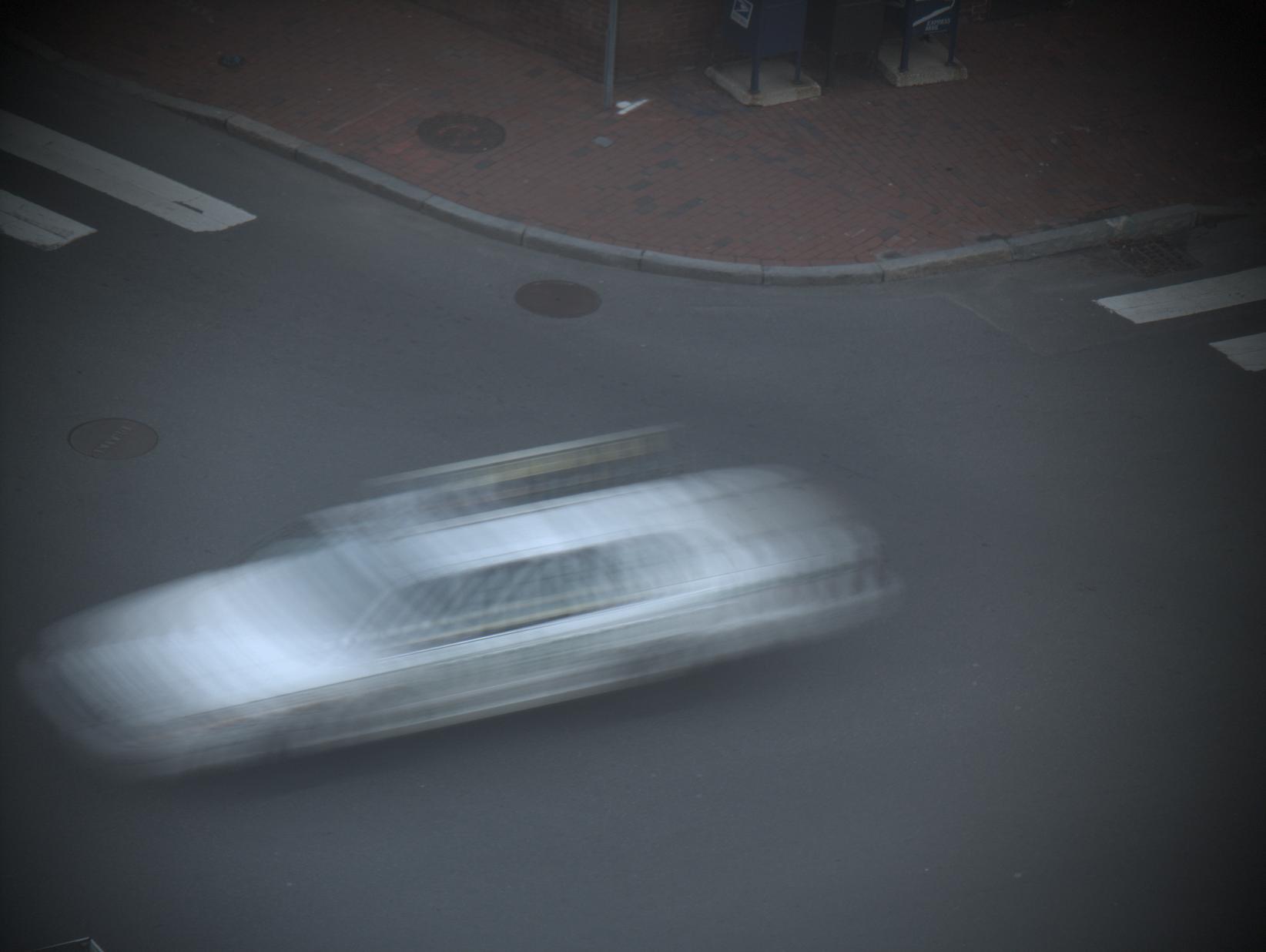
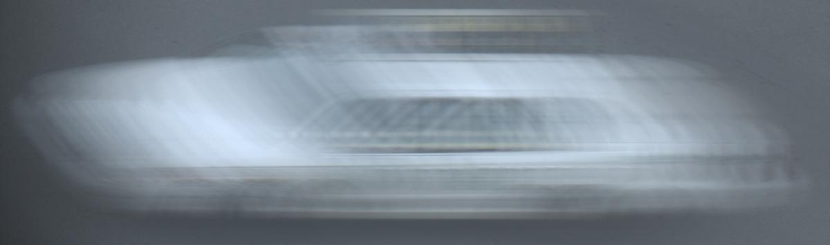


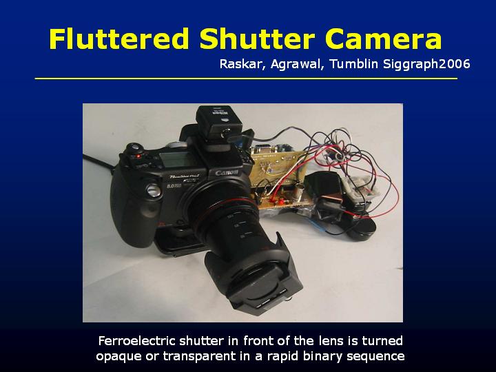
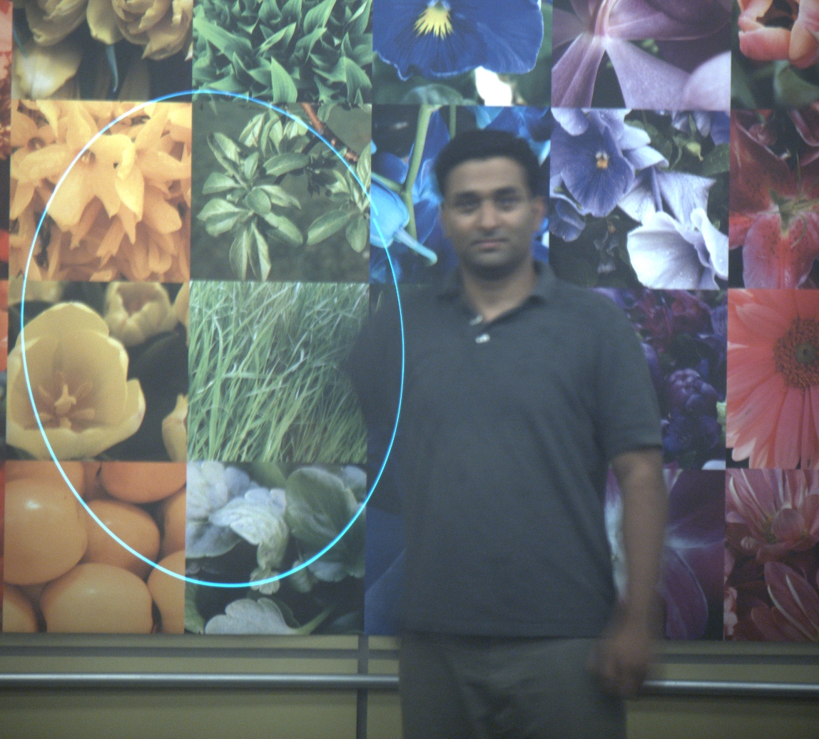
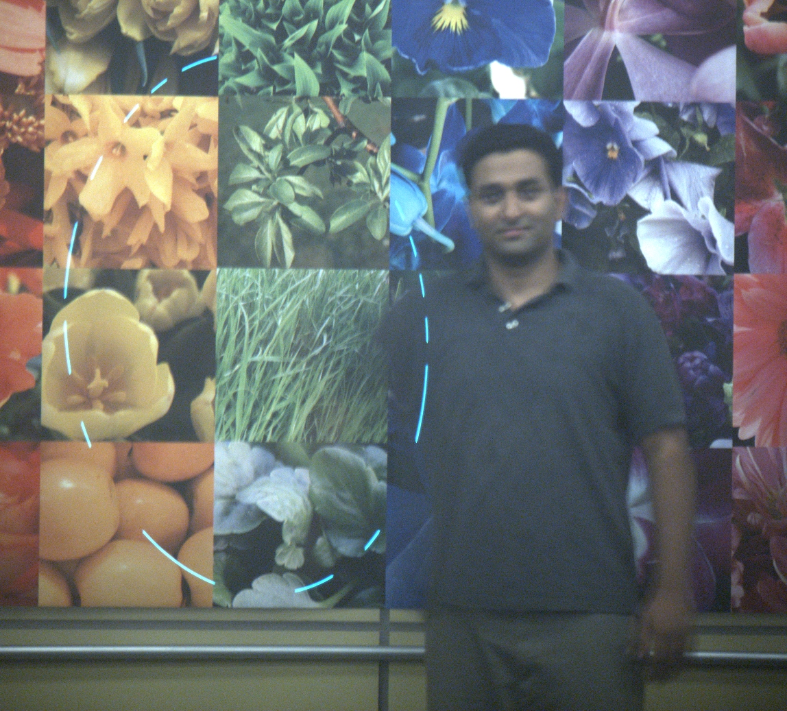
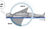
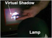


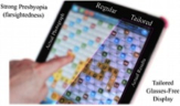
 Can we create a display that adapts itself to improve one’s eyesight? Top figure compares the view of a 2.5-diopter farsighted individual in regular and tailored displays. We use currently available inexpensive technologies to warp light fields to compensate for refractive errors and scattering sites in the eye.
 Vitor F. Pamplona, Manuel M. Oliveira.
 The letter G (a) on the retina of a 2D-coma, +5D-myopia (c), and cataract affected (d) subject. The holography G is virtualized at many depths (16cm < j < 25cm) from the eye. (b) shows how the image reaches the subject’s retina. (e) and (f) shows our computations for the light-field display. Giant ray circle reflects a 5mm-diameter pupil. Notice how the letter is deformed behind each section. Greenish circles in (e) and (f) highlight the cataract-avoiding feature of our algorithm.
 Input images (a) and how they are perceived on a tailored display by a farsighted subject (c). Column (b) shows how the subject sees the respective image on (a), with same size, at the same distance in a standard monitor.
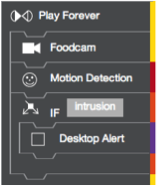
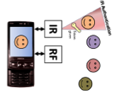
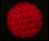

 Street Mapping Services such as Google Streetview: Shops use Bokodes to provide meta information to the trucks as they drive down the street taking pictures.
 Rear projected Microsoft Surface: Tiny Bokodes attached under physical objects placed on the table surface are used to decode position, identiï¬cation, and the angle the object (such as a stylus pen) makes with the surface.
 Multi-user interaction with a large display in a classroom or conference: The participants use Bokodes with unique identifiers to interact with displays from a distance.
 Crowd Gaming in Public Spaces: Participangs use Bokodes to control their characters on a shared display from a distance.
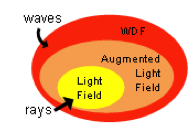
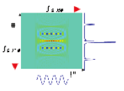
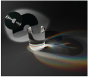
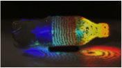
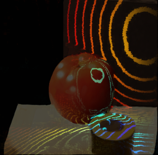
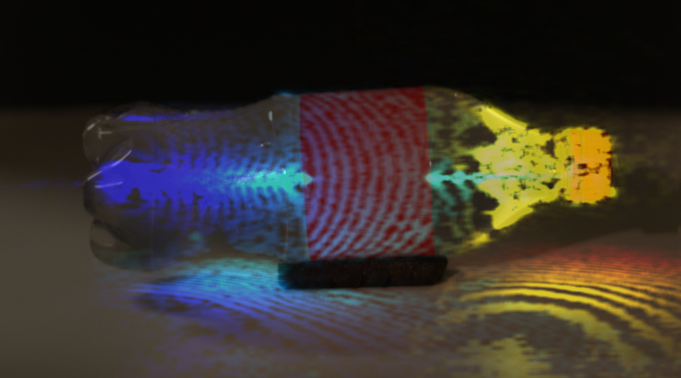


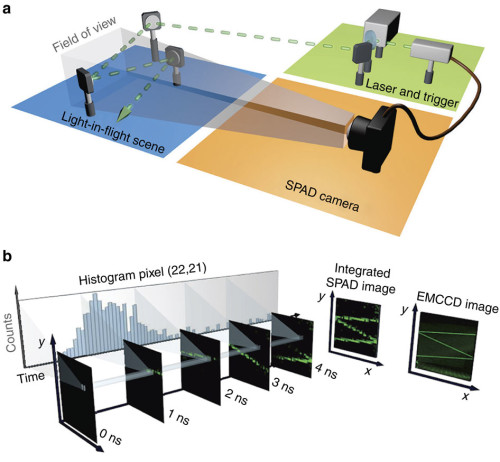

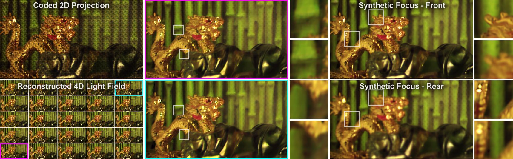
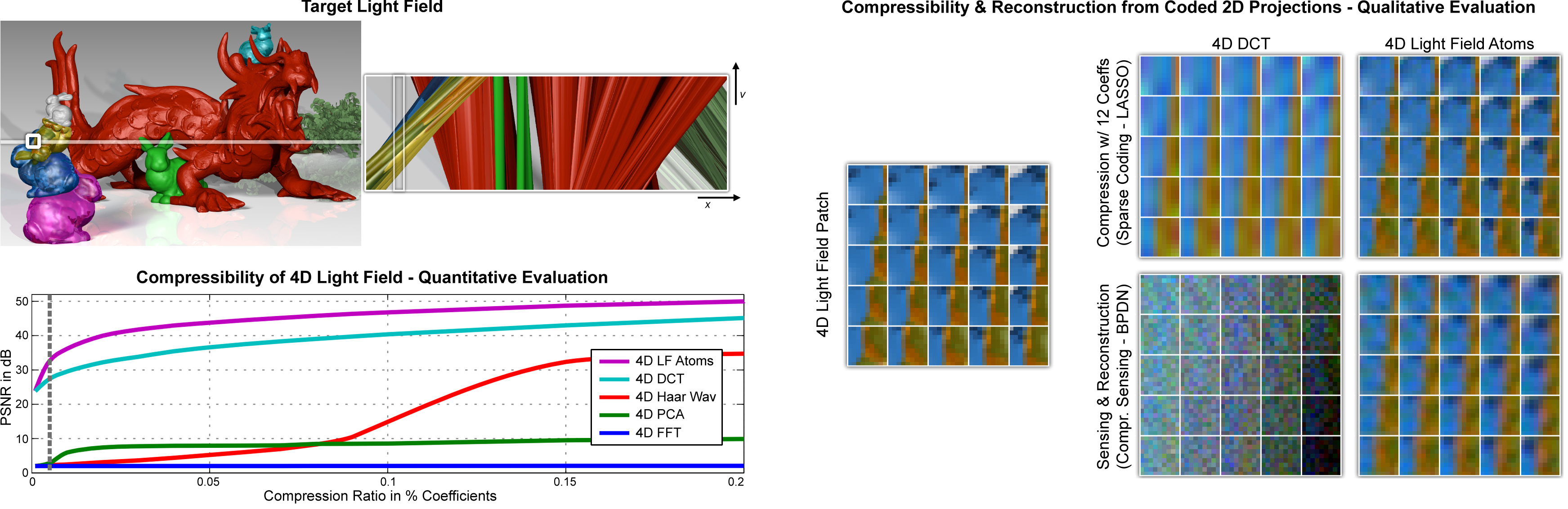
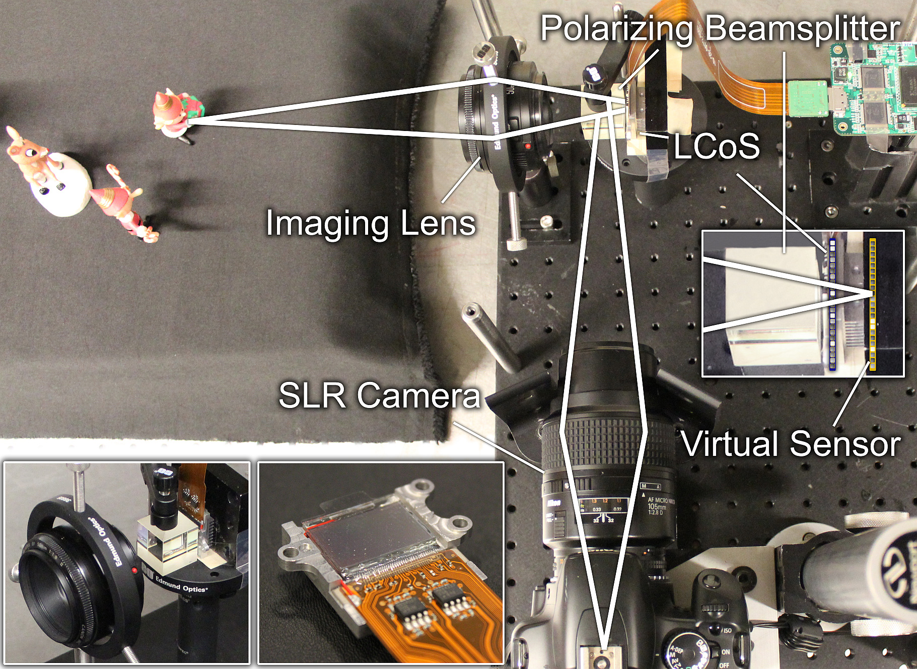
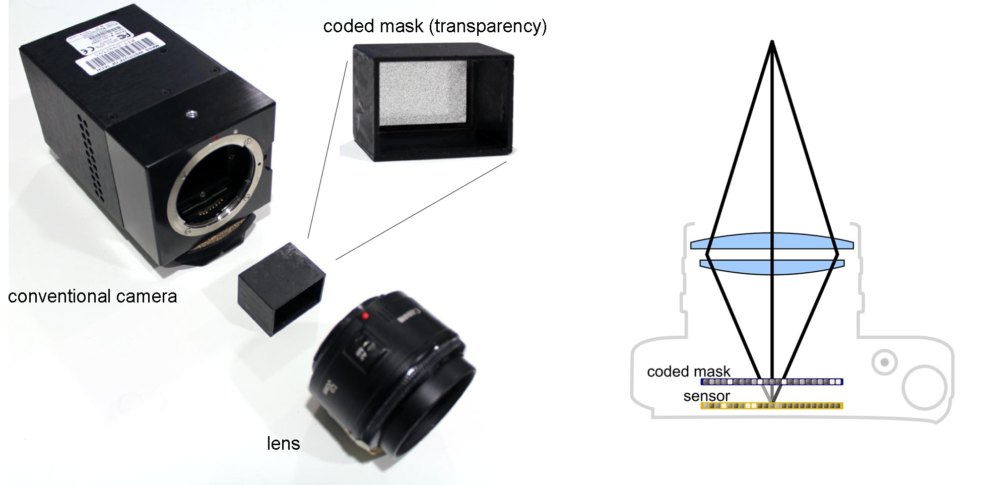

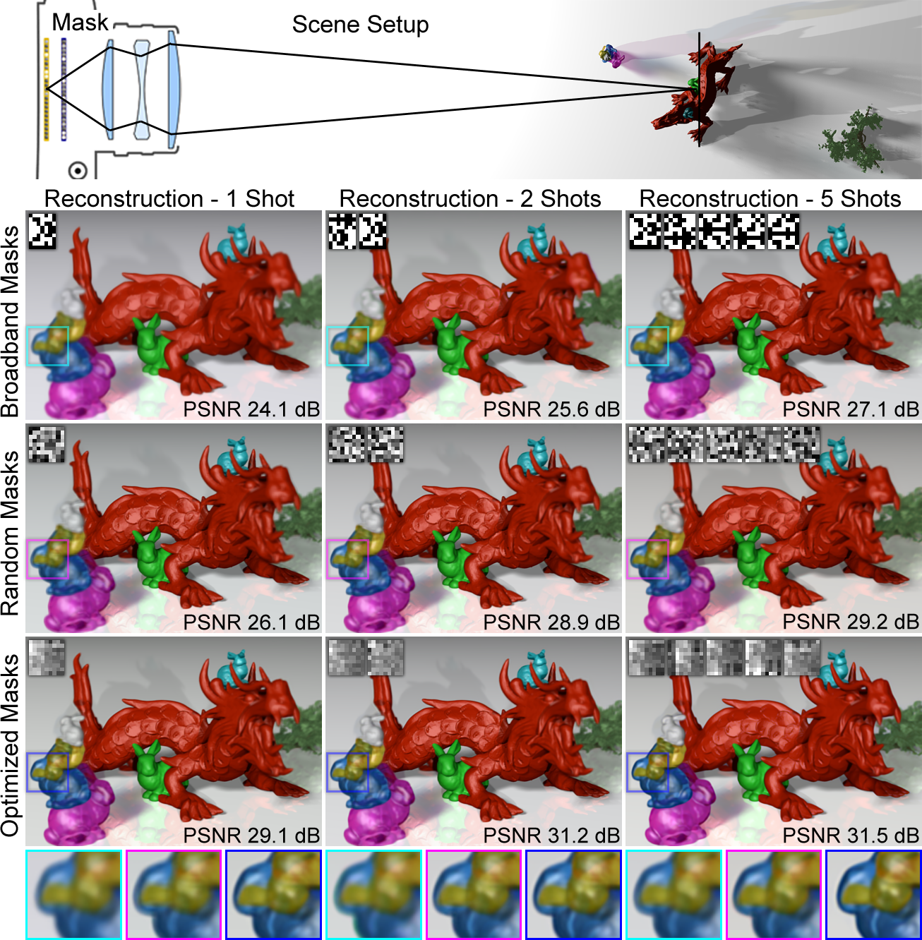
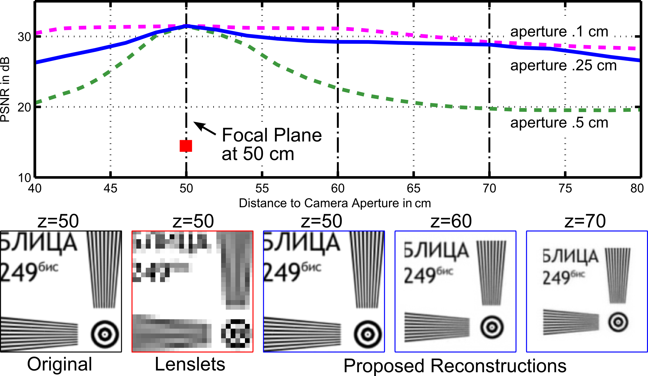
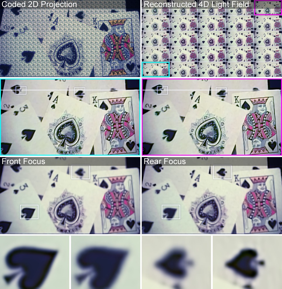
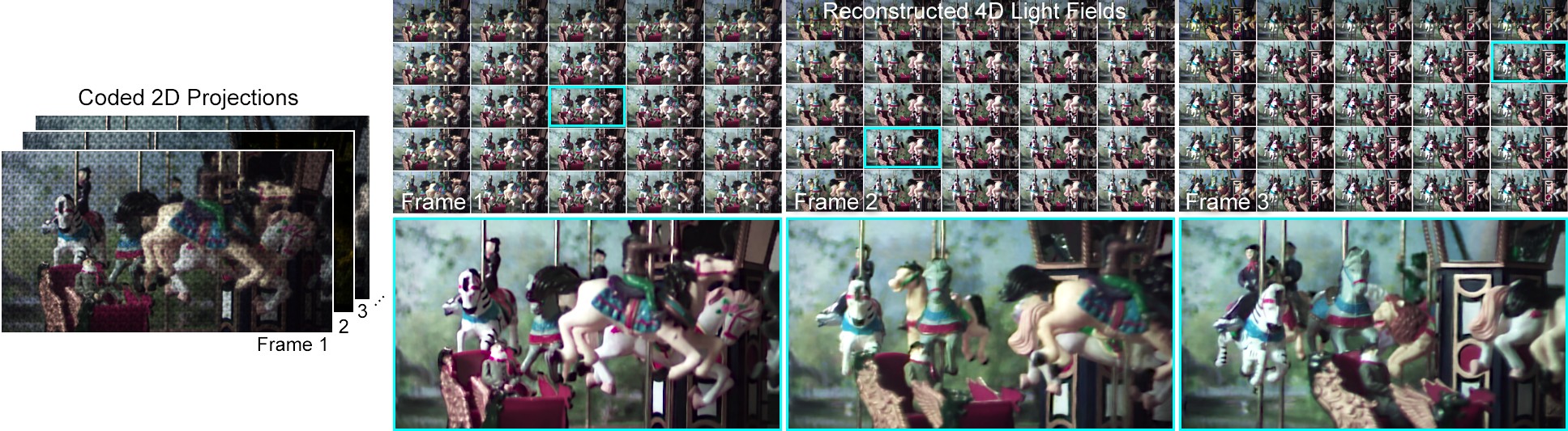
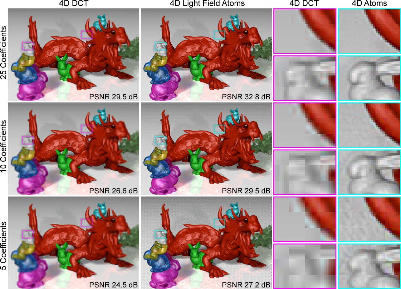
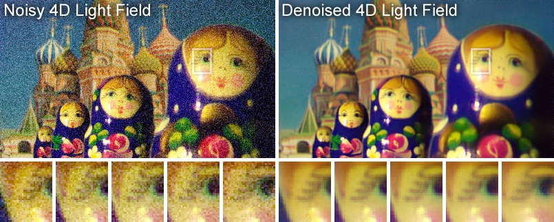
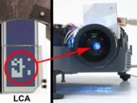
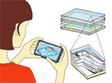
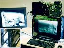
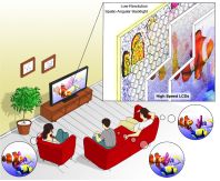
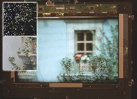
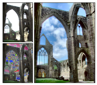

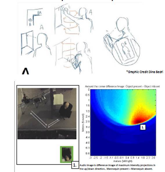

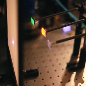
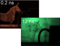
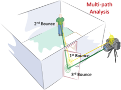
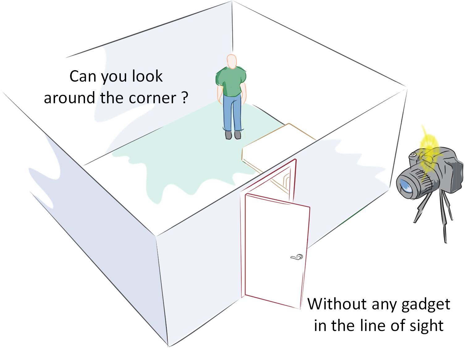
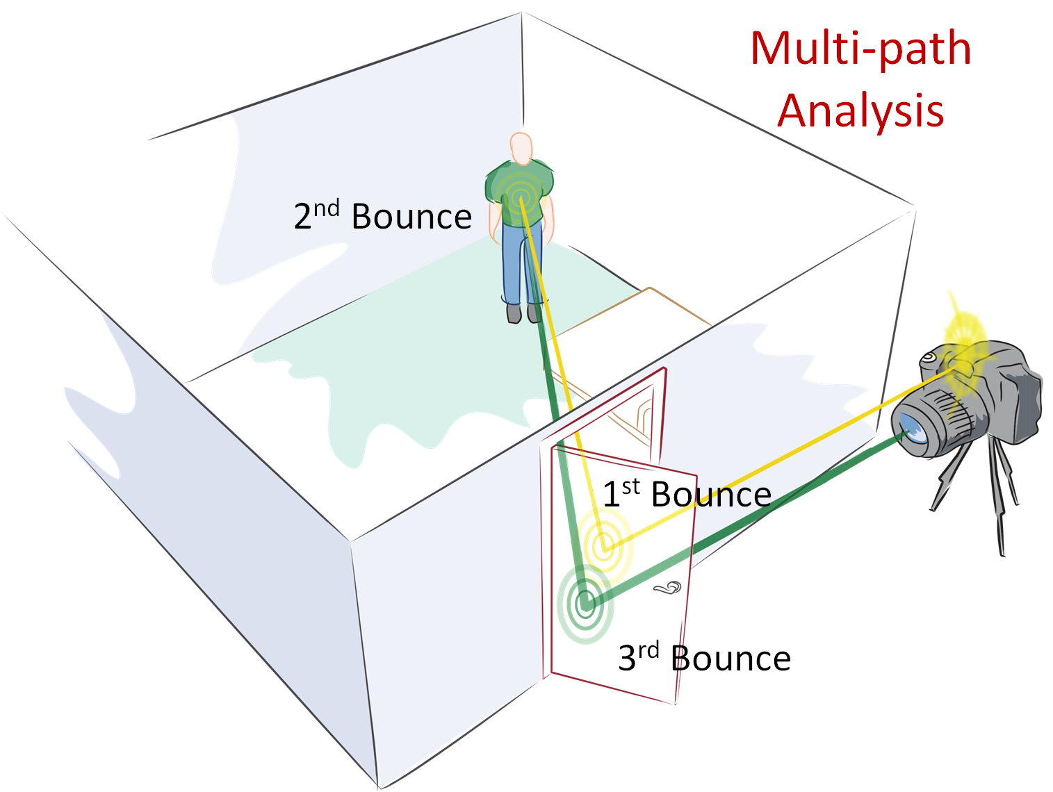
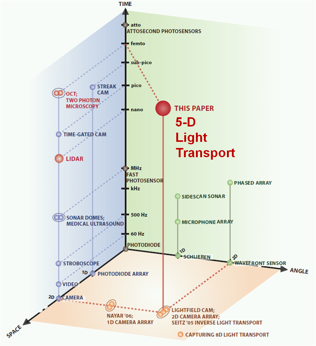
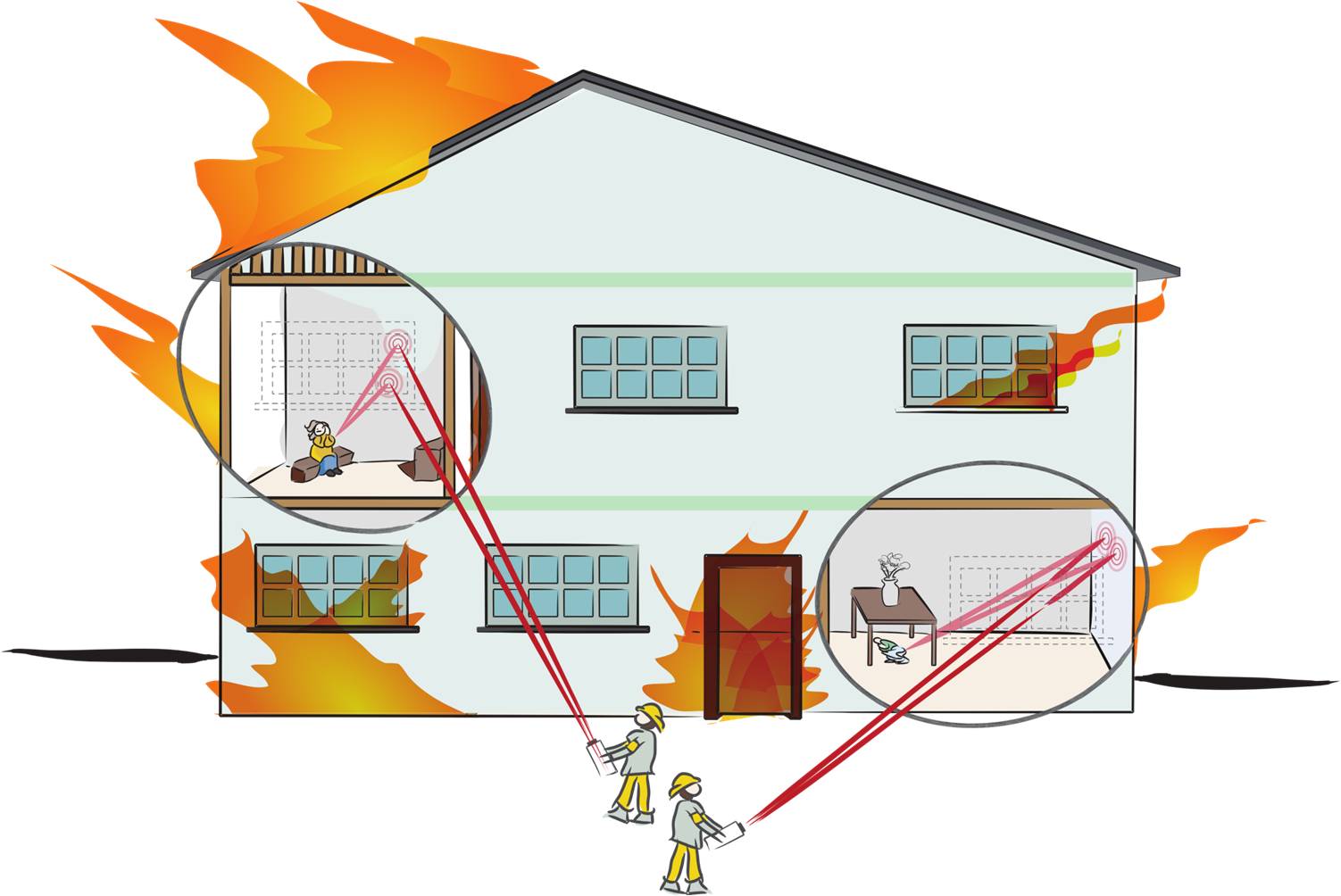
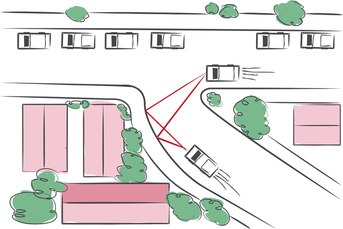 Avoiding collisions at blind corners for cars.
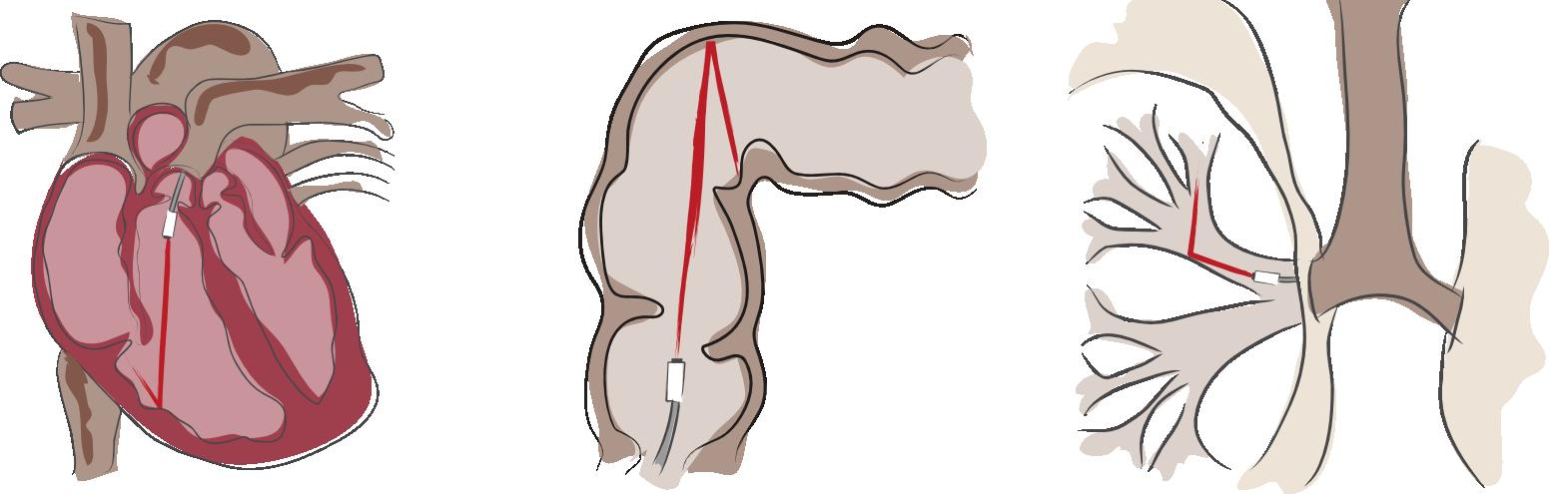
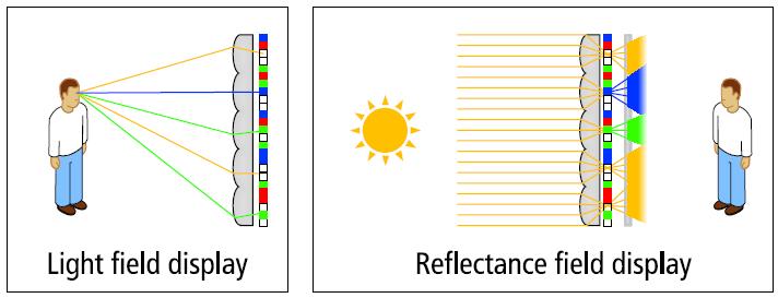


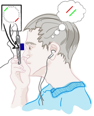

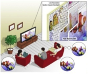
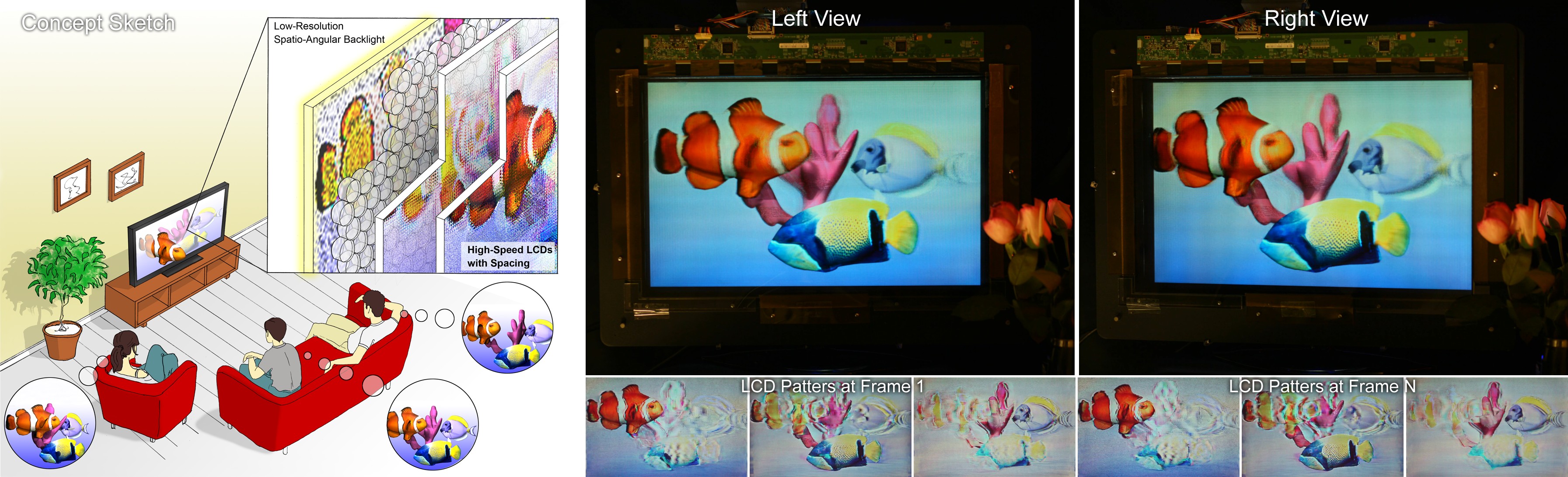

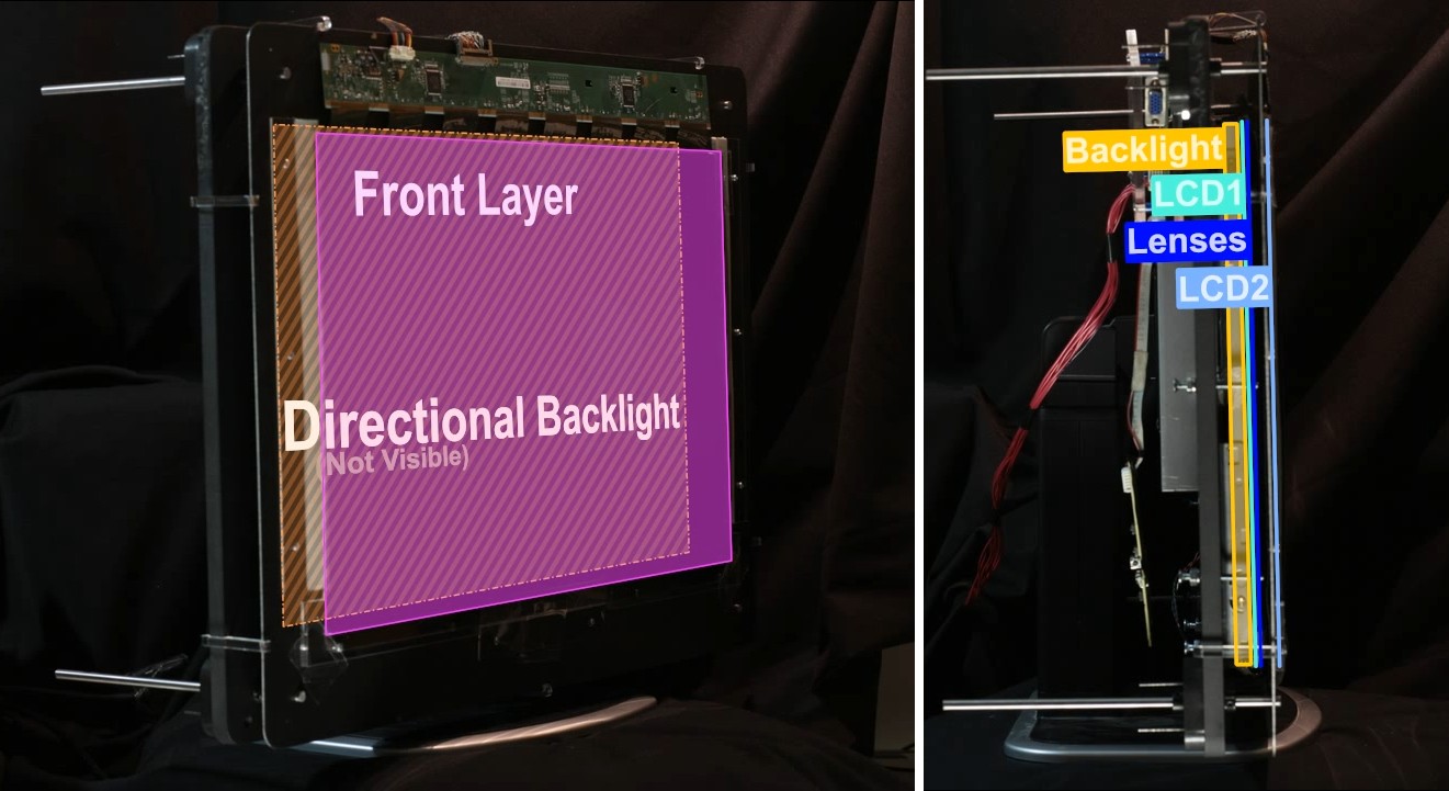
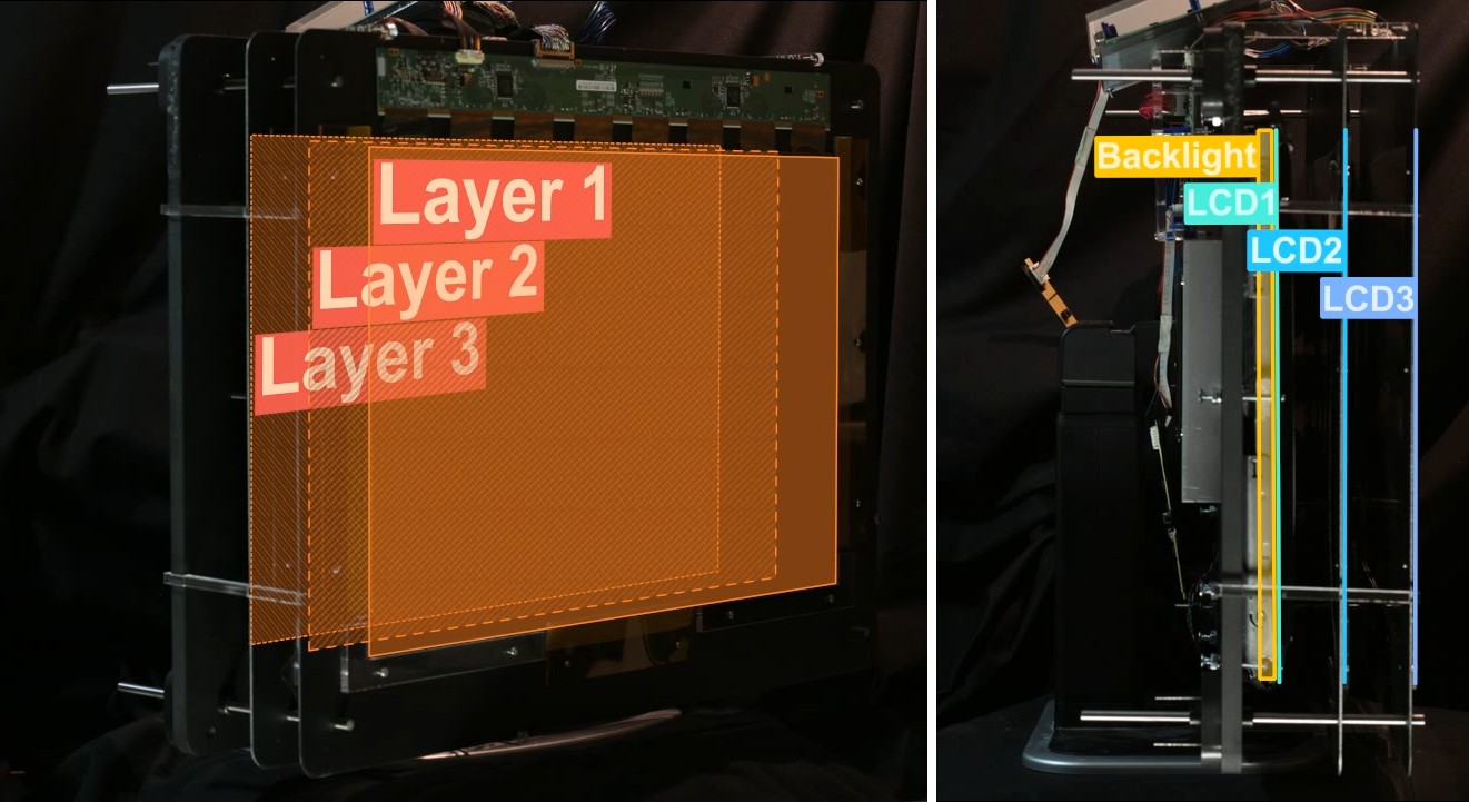
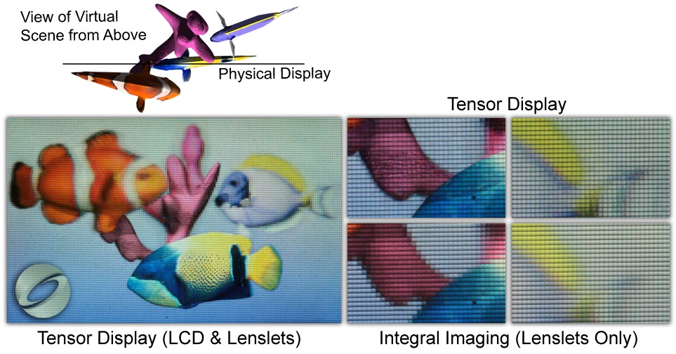
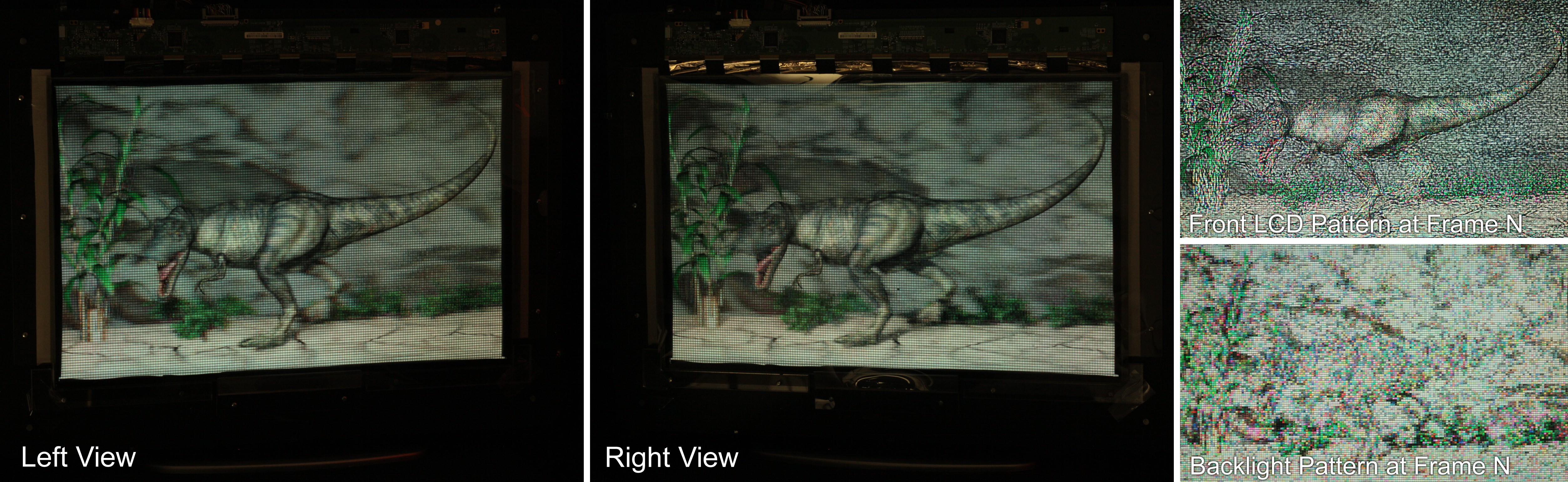

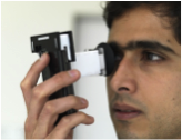


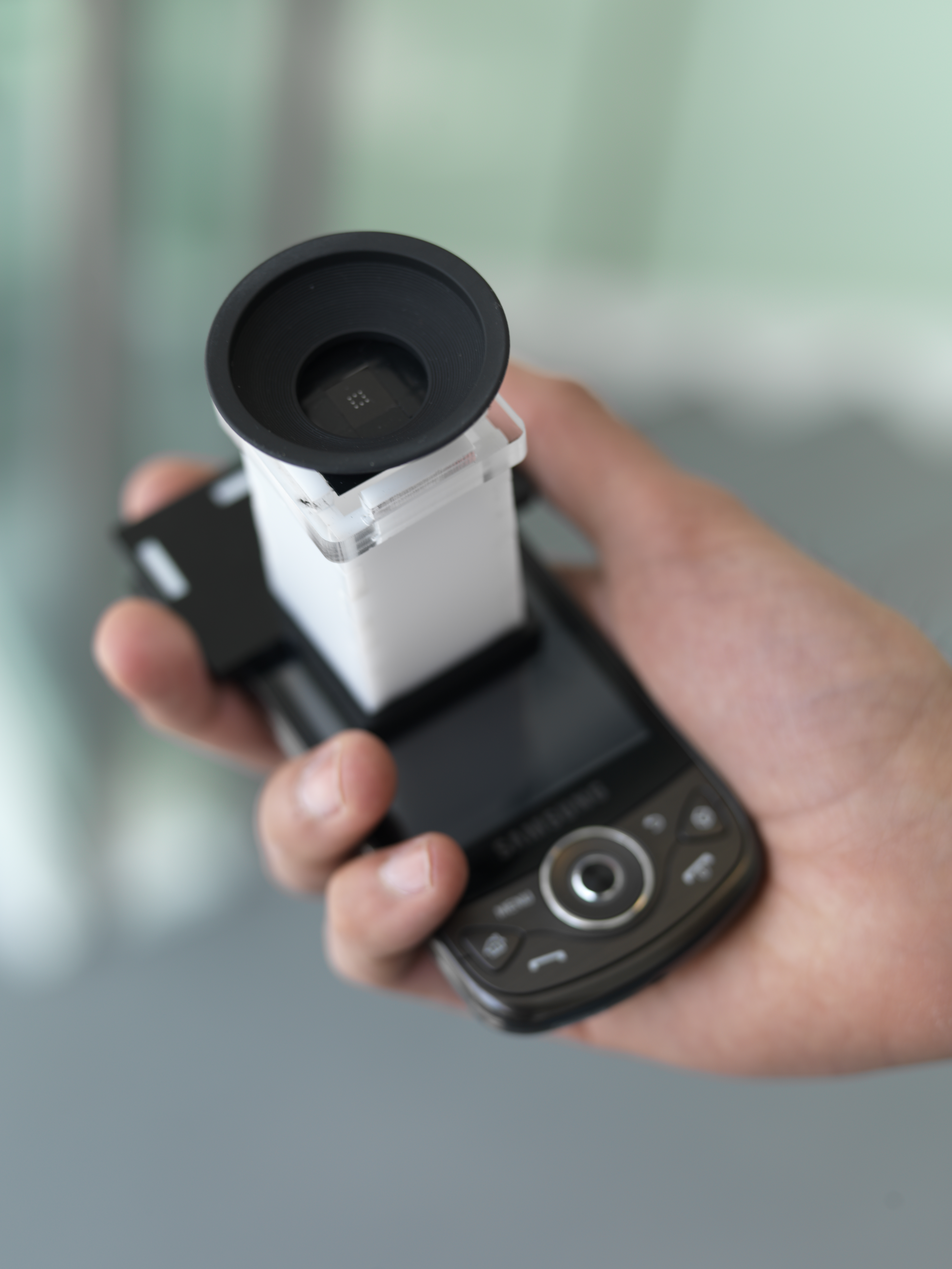


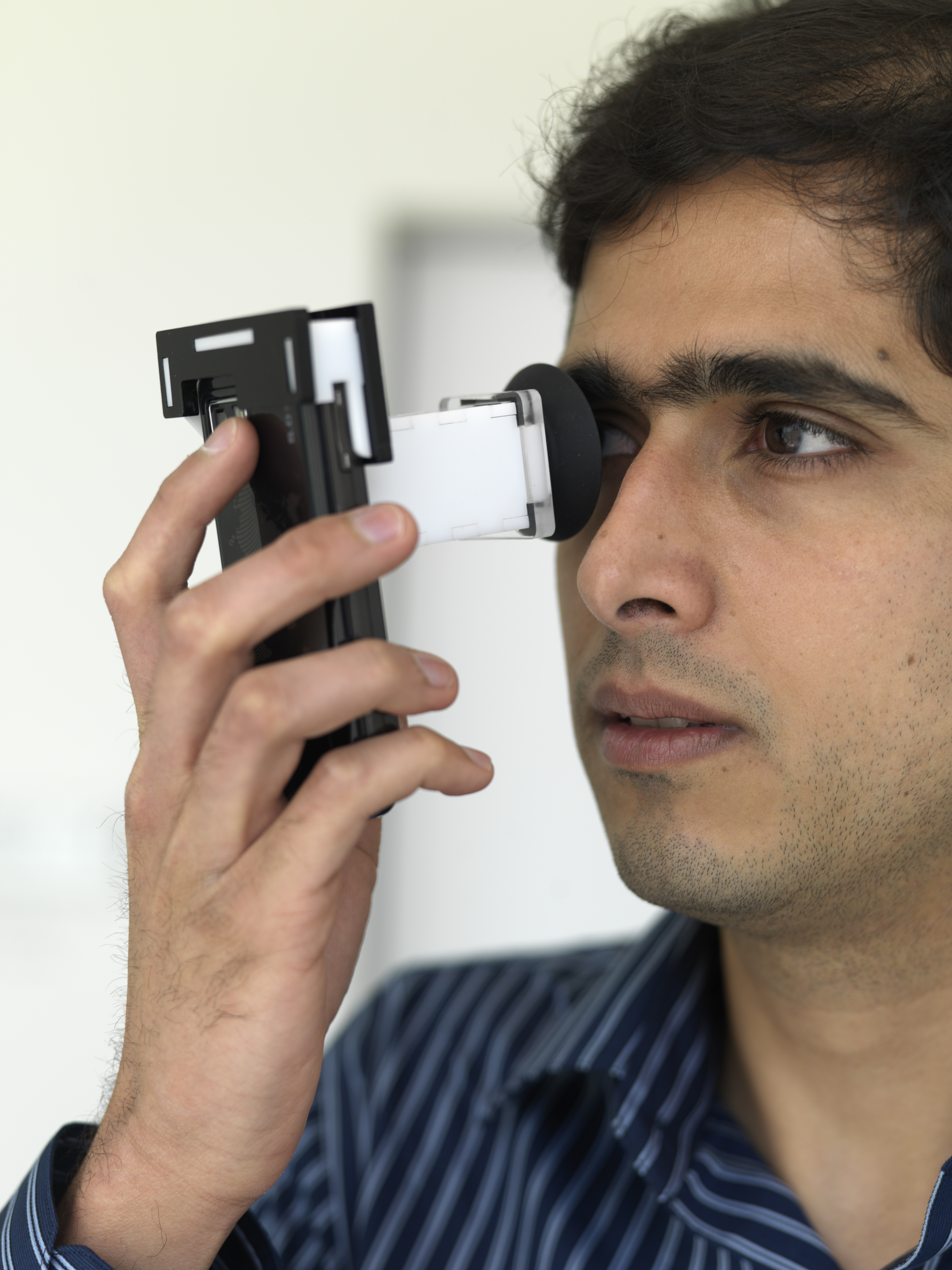
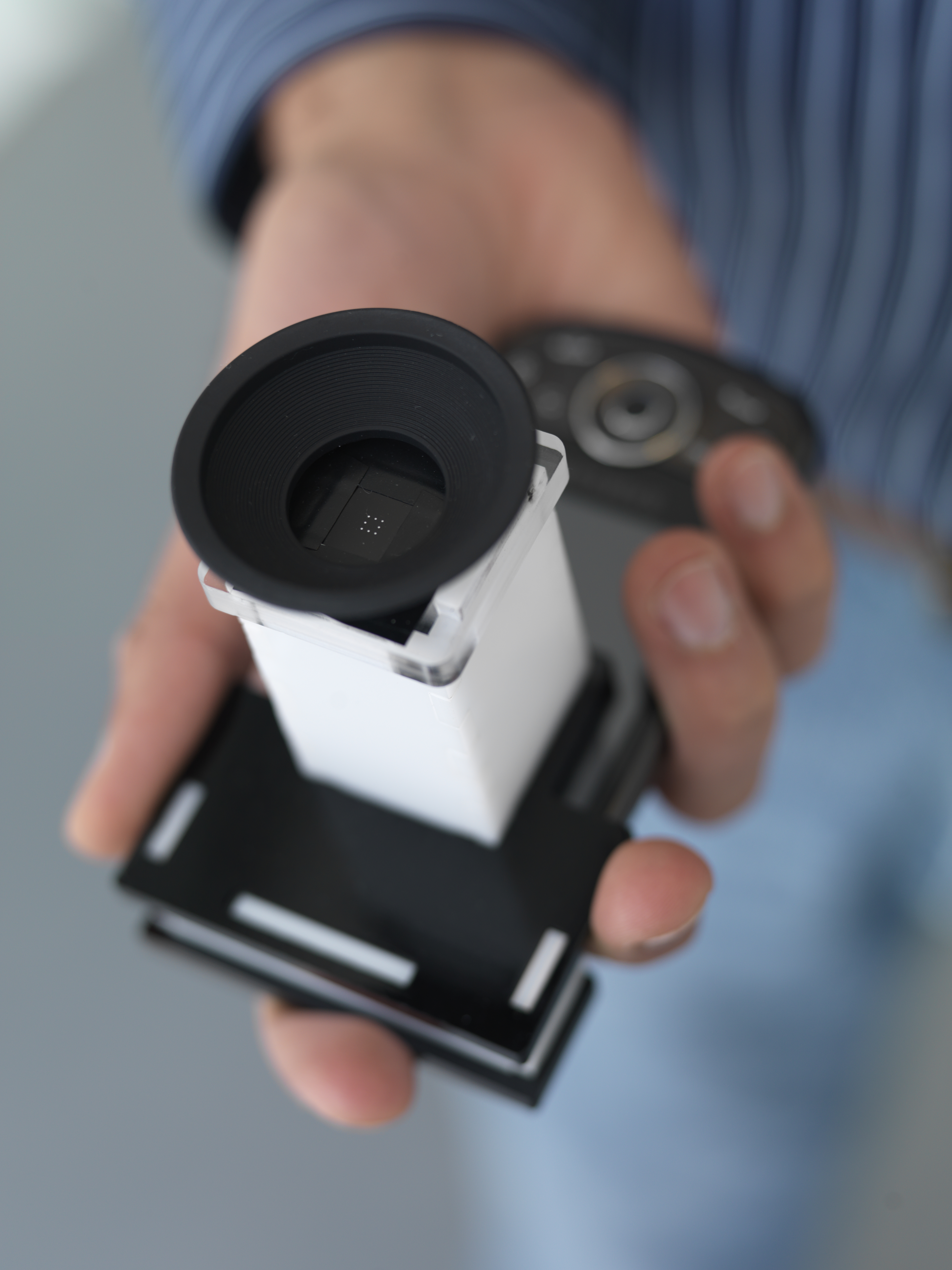


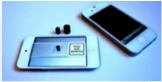
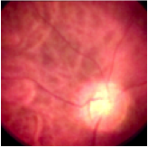
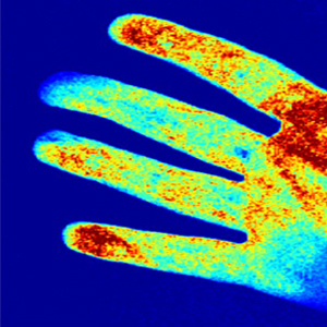
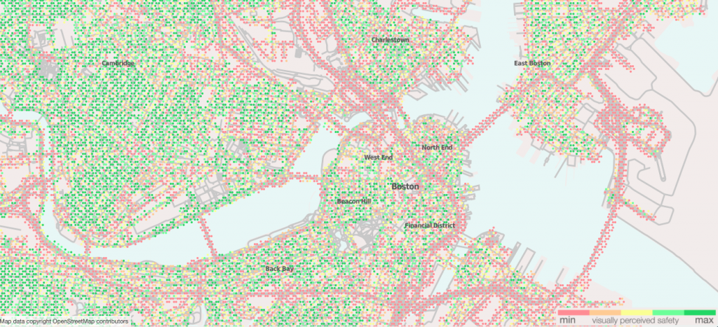


 Double curvature deformation. (A) Real images. (B) Simulations
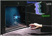


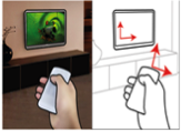
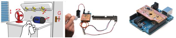 SpeckleEye describes the design and implementation of an embedded gesture and real-time motion tracking system using laser speckle. SpeckleEye is a low-cost, scalable, open source toolkit for embedded speckle sensing and gestural interaction with ubiquitous devices in the environment. We describe embedded speckle sensing hardware and firmware, a cross-platform gesture recognition library optimized to run on embedded processors, and a set of prototypes that illustrate the flexibility of our platform.
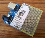

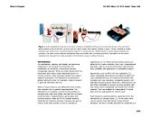

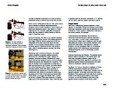
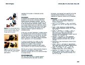
 SpeckleSense introduces a novel set of motion-sensing configurations based on laser speckle sensing that are particularly suitable for human-computer interaction. SpeckleSense is a technique for optical motion sensing with the following properties:
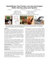
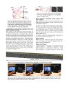
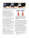
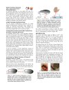
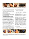
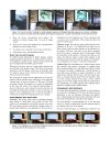
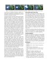
